
Description
Fiber Ferrule Inspection · Imaging system and software application or API
Fiber Ferrule Inspection System
A microscope-based imaging system with tester software or an API that inspects every optical fiber ferrule before it becomes a connector. It checks adhesive symmetry, end-face defects and cleanliness, fiber center offset and transmission losses, and returns pass or fail for each ferrule to your production line.

What it checks
Four tests in one station
Every ferrule end face is imaged and analysed, so a bad channel is found at the station, before the part is assembled into a connector, a transceiver or a network.
| Test | What it verifies | Why it matters |
|---|---|---|
| Symmetrical core adhesive | That the adhesive is installed symmetrically around the fiber inside the ferrule | Asymmetric adhesive points to a potting problem and can shift the fiber off center |
| Defects and cleanliness | Imperfections and contamination on the end face: scratches, chips, particles and residue | Contamination is the most common cause of connector loss and failure |
| Center offset | The offset between the optical center of the fiber core and the mechanical center of the ferrule | Two mated ferrules only line up if each core sits on its ferrule center |
| Transmittance and losses | How much light passes through each fiber and how much is lost | Turns a visual impression into a number you can accept or reject |
- Complete inspection: from adhesive symmetry to transmittance
- User-friendly software interface operators learn quickly
- Reliable, repeatable results with the same criteria on every ferrule
- An inspection record for every unit, for QA and traceability
Why offset matters
A micrometre of offset costs light
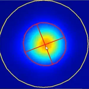
Light travels in the fiber core, but the connector is aligned by the mechanical ferrule around it. In single-mode fiber the light fills a nearly Gaussian mode only about 9–10 µm wide, so the coupling loss grows with the square of the combined offset of the two mated ferrules: IL [dB] ≈ 4.343 · (2d / MFD)².
| Combined lateral offset | Loss, MFD 9.2 µm (1310 nm) | Loss, MFD 10.4 µm (1550 nm) |
|---|---|---|
| 0.5 µm | 0.05 dB (98.8% coupled) | 0.04 dB (99.1% coupled) |
| 1.0 µm | 0.21 dB (95.4% coupled) | 0.16 dB (96.4% coupled) |
| 1.5 µm | 0.46 dB (89.9% coupled) | 0.36 dB (92.0% coupled) |
| 2.0 µm | 0.82 dB (82.8% coupled) | 0.64 dB (86.2% coupled) |
Lateral offset only; angular misalignment, end gaps and contamination add further loss. Try your own fiber and loss budget in the core offset to insertion loss calculator.
How it works
Image, measure, decide
- Image the end face
Cameras coupled to microscopes image the fiber surface and cross-section, with precise alignment and automatic focus for repeatable images.
- Measure automatically
Image-processing algorithms find the fiber and the ferrule in each image, measure the center offset and adhesive symmetry, and detect defects and contamination.
- Decide and log
Each ferrule gets a pass or fail against the test parameters you set, with transmission and losses per channel and a record for quality control.
| Result per ferrule | What you get | Used for |
|---|---|---|
| Center offset | Offset of the core from the ferrule center | Alignment and expected connection loss |
| Adhesive symmetry | Whether the adhesive around the fiber is symmetrical | Process control of the potting step |
| End-face condition | Defects and contamination found on the end face | Clean, rework or reject before mating |
| Transmittance and losses | Light transmitted and lost per channel | Channel acceptance |
| Pass/Fail | Against your customizable test parameters | Line decision and inspection record |
Integration level
Tester application, API or complete station
Tester application
Stand-alone inspection software for the lab or the production floor.
- Simple interface for operators
- Pass/fail per ferrule
- Inspection records for QA
Software API
For teams that run the inspection inside their own production software.
- Same image analysis as the application
- Results returned to your tester
- Customizable test parameters per fiber type
Complete station
A turnkey station adapted to your parts, volumes and limits.
- Multi-fiber parts, e.g. 8 ferrules per side (4 Tx, 4 Rx)
- Transmission and loss measurement per channel
- Setup and support by IZAK engineers
Need more than ferrules? We also build fiber cleaving testers, high-power fiber transmission testers and narrow-beam alignment tools: see optical fiber inspection testers for fiber production.
See it work
Watch: the fiber ferrule inspection system
IZAK demo: the system inspects a set of 8 ferrules on each side of the unit under test, 4 transmit (Tx) and 4 receive (Rx) channels, as used in parallel optical-communication links.
IZAK demo: image processing for optical fiber inspection, from the end-face image to the measured values and the pass/fail result per channel.
Applications
Where it is used
- Quality control in fiber and connector production
- Incoming inspection and final QA of fiber assemblies
- Multi-channel parts for parallel optical links
- Process optimization: adhesive, polishing and cleaning steps
- Research and development of new fiber types
- Telecom component production
Resources
Guides and related systems
- How the ferrule inspection system worksOffset, cleanliness and transmission, with a loss calculator
- Fiber inspection testers for productionFerrule, cleave, transmission and alignment testers
- A beginner’s guide to fiber opticsModes, losses and connectors explained
- Fiber optic designCustom fiber sensing, sampling and test
FAQ
Frequently asked questions
What do you need from us to propose a ferrule inspection system?
The connector or ferrule type, single fiber or multi-fiber, single-mode or multimode, your volumes and cycle time, and the limits you test to. Sample parts help most. From that we propose a demonstration plan and the integration level: tester application, API or complete station.
Can it inspect multi-fiber parts?
Yes. In the demonstration shown above, the system inspects a set of 8 ferrules on each side of the unit under test, 4 transmit and 4 receive channels, and reports a result for each channel.
Can the test limits be set to our specification?
Yes. The test parameters are customizable for different fiber types and standards across your product range, including the offset limit, the end-face criteria and the transmission limits.
Does it replace an end-face cleaning step?
No. It finds and records contamination and defects so that a ferrule is cleaned, reworked or rejected before it is mated. A dirty end face can damage both connectors when they are mated, so inspection comes before connection.
Can the results go into our production or traceability system?
Yes. With the API, the inspection runs inside your own software and returns the result of every ferrule, and the data logging keeps a detailed record for quality control, process optimization and compliance.
Inspect every ferrule before it ships
Tell us the connector types, the volumes and the limits you test to. We reply with a demonstration plan and a configuration proposal.
Tzachi Sabati
CEO, IZAK Scientific
Physicist specializing in photonics and quantum technologies, with deep expertise in quantum sensors and advanced optical systems. Leads the Advanced Quantum Lab course at the Technion, bridging academic excellence with industry innovation. At IZAK Scientific, provides cutting-edge photonics-based solutions, developing customized inspection and sensing systems for R&D and production. Passionate about advancing quantum sensing applications and integrating novel technologies to meet industry needs.