

In short
- Ellipticity is a snapshot, astigmatism is a property of the beam. Ellipticity is the ratio of the two principal widths in one plane. Laser beam astigmatism means the two principal axes have their waists in different places, or behave differently as the beam propagates.
- A round spot does not prove a stigmatic beam. An astigmatic beam can be perfectly round in a plane near its waists and often looks round again in the far field.
- Measure on the principal axes. Widths taken along the camera rows and columns can hide a tilted ellipse completely: a 0.60 ellipse at 45° reads as 1.00.
- Measure the caustic, not one plane. Profile the beam at ten or more planes through the focus, fit each principal axis on its own, and report both waist positions, both waist widths and the astigmatic difference.
Ellipticity and laser beam astigmatism are not the same thing
Laser beam astigmatism and ellipticity are often used as if they meant the same thing. They do not, and mixing them up is one of the most common reasons a focusing or fiber-coupling design misses its target. Laser diodes, slab and solid-state lasers with thermal lensing, and any system with tilted lenses or mirrors produce beams that need both numbers.
Ellipticity describes the beam in one plane. ISO 11146-1 defines it as the ratio of the smaller to the larger second-moment (D4σ) width along the principal axes of the power density distribution. A profile with ellipticity above 0.87 may be regarded as circular.
Astigmatism describes how the beam propagates. In a stigmatic beam both principal axes focus at the same place, with the same waist width and divergence, so the profile stays round along the whole path. In an astigmatic beam they do not. ISO 11146 separates three cases:
| Beam type | What it means | Typical sources | How to measure |
|---|---|---|---|
| Stigmatic | Round in every plane; one waist position, one width, one divergence | Well-aligned TEM00 lasers, single-mode fiber outputs | ISO 11146-1, one width per plane |
| Simple astigmatic | Fixed principal axes; each axis has its own waist position, waist width and M² | Edge-emitting laser diodes, slab lasers, cylindrical or tilted optics | ISO 11146-1, fit x′ and y′ separately |
| General astigmatic | Principal axes rotate as the beam propagates (a twisted beam) | Non-orthogonal cylindrical optics, misaligned multi-element systems | ISO 11146-2, the full set of second moments |
Most lasers in practical use are stigmatic or simple astigmatic. The rest of this article covers those two cases, which a camera-based beam profiler and a translation stage can handle.
Measure ellipticity on the principal axes, not the camera axes
A camera beam profiler computes three second moments from each frame: ⟨x²⟩, ⟨y²⟩ and the mixed moment ⟨xy⟩, all taken about the centroid. The D4σ widths along the camera rows and columns are 4√⟨x²⟩ and 4√⟨y²⟩. They describe the beam correctly only when the ellipse happens to be aligned with the sensor.
The principal axes follow from all three moments. The azimuth angle of the ellipse is
φ = ½ · atan2( 2⟨xy⟩ , ⟨x²⟩ − ⟨y²⟩ )
and the two principal widths are
dx′,y′ = 2√2 · { ⟨x²⟩ + ⟨y²⟩ ± γ · [ (⟨x²⟩ − ⟨y²⟩)² + 4⟨xy⟩² ]½ }½, with γ = sign(⟨x²⟩ − ⟨y²⟩).
The table shows why this matters. It is the same elliptical beam, 2.0 mm by 1.2 mm (ellipticity 0.60), turned on the sensor:
| Rotation on the sensor | Width along rows / columns | Ellipticity from camera axes | Ellipticity on principal axes |
|---|---|---|---|
| 0° | 2.00 / 1.20 mm | 0.60 | 0.60 |
| 30° | 1.83 / 1.44 mm | 0.79 | 0.60 |
| 45° | 1.65 / 1.65 mm | 1.00 | 0.60 |
At 45° the row and column widths are identical, and a test that uses them would pass a clearly elliptical beam as round. Always report ellipticity and widths on the principal axes, together with the azimuth angle. When the ellipticity is close to 1 the azimuth becomes noisy and has little meaning; that is expected, not a fault. The same second-moment rules, and the background and analysis-area settings that make them reliable, are covered in our guide to laser beam width definitions.
How to measure laser beam astigmatism, step by step
Astigmatism cannot be read from one profile. It is found from the caustic, the beam width as a function of position through a focus, measured separately for each principal axis. The procedure is the same one used for M², so if you already follow our M² measurement guide you have most of the set-up.
- Create an accessible waist. Focus the beam with a well-corrected lens of long enough focal length that the Rayleigh length spans several millimetres. Keep the lens on-axis and untilted: a tilted lens adds astigmatism of its own.
- Attenuate without distortion. Use wedged samplers or reflective attenuators sized for the power at the sensor, and check that nothing clips or saturates at the waist, where the power density is highest.
- Scan through the focus. Mount the profiler on a rail or stage and record at least ten planes: about half within one Rayleigh length of the waist, and about half beyond two Rayleigh lengths, as ISO 11146 recommends. For an astigmatic beam, cover both waists with this rule.
- Check the azimuth in every plane. If the principal axes keep the same orientation (within the noise of near-round frames), the beam is simple astigmatic. If they rotate steadily through the caustic, the beam is general astigmatic and needs the ISO 11146-2 method.
- Fit each principal axis on its own. Fit dx′(z)² and dy′(z)² to the hyperbola d(z)² = d0² + θ²(z − z0)². Each fit gives a waist width d0, a waist position z0, a divergence θ and M² = π·d0·θ / (4λ).
- Report the astigmatic difference. Δz = z0y′ − z0x′. Divide it by the mean Rayleigh length to see how much it matters: the same 1 mm is negligible for a beam with a 50 mm Rayleigh length and dominant for one with 1 mm.
The full-angle divergence of each axis can also be measured directly in the far field or at the focal plane of a lens; see how to measure laser beam divergence.
Why a few micrometres at the chip become millimetres at the focus
Edge-emitting laser diodes are the classic astigmatic source: in the fast axis the beam behaves as if it comes from the facet, while in the slow axis the apparent source can sit some distance behind it. The difference at the chip is small, but optics magnify it. Lateral magnification m scales widths; longitudinal magnification scales distances along the axis by about m².
Suppose a diode with 10 µm of astigmatic distance is collimated by a 4.5 mm lens and refocused by a 100 mm lens. The lateral magnification is 100 / 4.5 = 22.2, so the longitudinal magnification is about 494. The two waists at the focus are now about 4.9 mm apart. A spot that looks round on a quick check may be the plane of least confusion between two line-like foci, and a fiber or a sample placed there couples or processes far worse than the waist widths suggest.
Astigmatic beam caustic calculator
Enter the waist width, M² and waist position of each principal axis, from your caustic fit or a design model. The calculator shows both widths and the ellipticity at any plane, where the beam looks round, the astigmatic difference, and whether the beam stays above the ISO 0.87 circularity limit along the whole path.
Paraxial model of a simple astigmatic beam: each principal axis follows d(z)² = d0² + θ²(z − z0)² with θ = 4M²λ / (πd0). Widths are second-moment (D4σ) diameters. Round planes are listed within ten mean Rayleigh lengths of the waists. Not valid for general astigmatic (twisted) beams.
Worked example: an 808 nm diode beam at the focus
A collimated 808 nm diode is focused by a lens. A caustic scan with the profiler on a rail gives, along the principal axes:
- Axis x′: waist 50 µm, M² = 1.1, waist at z = 0.
- Axis y′: waist 70 µm, M² = 1.5, waist at z = +1.5 mm.
Rayleigh lengths. zR = πd0² / (4M²λ) gives 2.21 mm for x′ and 3.18 mm for y′. The full divergences are almost equal, 22.6 and 22.0 mrad.
Astigmatic difference. Δz = 1.5 mm, or 0.56 of the mean Rayleigh length of 2.69 mm. This is a strongly astigmatic beam.
At the x′ waist (z = 0). dx′ = 50 µm and dy′ = 70 × √(1 + (1.5 / 3.18)²) = 77.4 µm. Ellipticity 0.65: clearly elliptical.
At z = +2.30 mm. Both widths are 72.2 µm. Ellipticity 1.00. A single profile taken here would report a perfectly round beam.
In the far field. Ellipticity tends to the ratio of the divergences, 22.0 / 22.6 = 0.97, which is again “circular” by the 0.87 rule.
Through the whole caustic. The lowest ellipticity is about 0.62, at z ≈ −0.84 mm, on the lens side of the x′ waist. Two of the three single-plane checks would have passed this beam as round. Only the caustic shows the 1.5 mm separation between the waists, and with it the fact that no plane gives the smallest spot on both axes at once.
Try it in the calculator: the first preset reproduces these numbers, and the second jumps to the round plane. To size the focus of a stigmatic beam instead, use the Gaussian beam calculator.
Common astigmatism and ellipticity measurement mistakes
Judging astigmatism from one planefalse “round”
An astigmatic beam with separated waists is often round in some plane near the focus, and can read round in the far field too. Measure the caustic and report both waist positions.
Using camera-axis widthshidden ellipse
Row and column widths understate ellipticity whenever the beam is rotated, up to complete loss at 45°. Use the principal axes and log the azimuth.
Fitting one hyperbola to an “average” widthwrong M² and waist
Averaging x′ and y′ before the fit blends two waists into one that does not exist. Fit each principal axis separately.
Too few pixels across the waistbeam reads rounder
With fewer than about ten pixels across the smallest axis, pixelation and noise pull the ellipticity towards 1. Use a longer focal length or a profiler with smaller pixels.
Background left in the second momentsinflated widths
Residual offset adds the same amount to both axes and makes the beam look rounder. Subtract the background and use a sensible analysis area before you trust any ellipticity.
Tilted lens or attenuator in the set-upadded astigmatism
A lens tilted by a few degrees adds astigmatism of its own. Align the focusing lens normal to the beam and keep plates in a converging beam to a minimum.
IZAK products for this application
The IZAK Laser Beam Profiler software reports ISO 11146 second-moment widths, ellipticity, orientation and centroid in every frame. Mounted on a rail or stage and moved through the focus, it gives the per-plane data for a caustic fit, and its pass/fail and API functions let a production station test ellipticity limits automatically.
 UV to LWIRLaser Beam ProfilersUV–VIS–NIR 300–1100 nm, SWIR up to 2.05 µm, MWIR 1.5–5.7 µm and LWIR 7.7–12 µm, with ellipticity, orientation and test modes.View product →
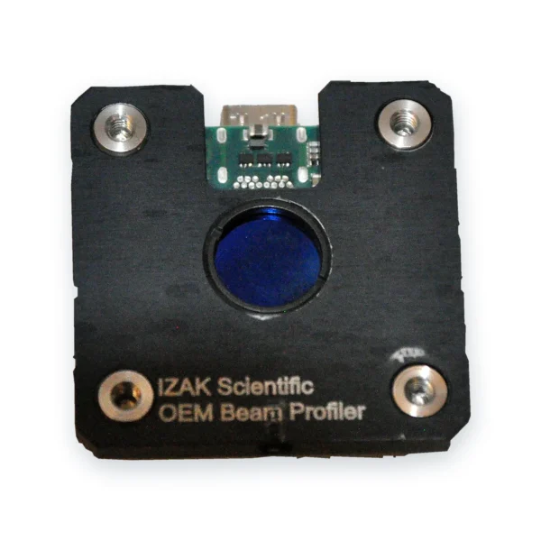 For testers and machinesOEM Board-Level Beam ProfilersUSB 3 powered modules from 7 g, light enough for a motorised stage, with pass/fail, logging and an API.View product →
Diode lasers from 300 to 1100 nm are covered by the UV–VIS–NIR beam profilers; for 1310 and 1550 nm diodes see the SWIR beam profilers. Need a complete caustic or diode test station? See custom electro-optical test systems or book a beam profiler consultation.
Frequently asked questions
QWhat is the difference between ellipticity and astigmatism of a laser beam?
QHow do you measure laser beam astigmatism?
QWhy do laser diodes have astigmatic beams?
References
- ISO 11146-1:2021, Lasers and laser-related equipment — Test methods for laser beam widths, divergence angles and beam propagation ratios — Part 1: Stigmatic and simple astigmatic beams.
- ISO 11146-2:2021, Part 2: General astigmatic beams.
- ISO/TR 11146-3, Part 3: Intrinsic and geometrical laser beam classification, propagation and details of test methods.
Tzachi Sabati
CEO, IZAK Scientific
Physicist specializing in photonics and quantum technologies, with deep expertise in quantum sensors and advanced optical systems. Leads the Advanced Quantum Lab course at the Technion, bridging academic excellence with industry innovation. At IZAK Scientific, provides cutting-edge photonics-based solutions, developing customized inspection and sensing systems for R&D and production. Passionate about advancing quantum sensing applications and integrating novel technologies to meet industry needs.
Get new IZAK guides and tools by email
One short email a month: new technical articles, free calculators and product updates in laser measurement and electro-optics. No spam, unsubscribe anytime.
