

In short
- Fiber coupling efficiency into a multimode fiber rests on two numbers: the focused spot must fit the core, and the focusing cone must fit the fiber NA. Keep both at about 70–80% of the limit, not 100%.
- The beam parameter product tells you in advance if it can work. If M²λ/π is larger than the fiber’s core radius × NA, no lens will couple the beam efficiently.
- Single-mode coupling is a mode-matching problem. Spot size, lateral offset and tilt multiply; a 1 µm offset already costs several percent at 1550 nm.
- Measure, do not assume. Use a reference (bypass) power reading and a fiber-output reading with the same calibrated detector, and inspect both end faces first.
Every fiber-delivered laser, from a surgical laser to an industrial marking head or a telecom transmitter, depends on one figure: how much of the laser power actually enters the fiber and leaves it at the far end. Fiber coupling efficiency is that ratio. Get it wrong and the treatment fluence is low, the connector burns or the link budget fails. This application note explains the physics that limits coupling into multimode and single-mode fibers, gives the design equations with a worked example, includes a free fiber coupling calculator, and shows how to measure the result in the lab or on a production line.
What limits fiber coupling efficiency
Coupling efficiency η is the power guided by the fiber divided by the power incident on its input face. The total transmission of a fiber assembly is η multiplied by the losses inside the fiber and at its output. In practice, the loss budget has six terms:
| Loss mechanism | Typical size | How to check it |
|---|---|---|
| Spot larger than the core (multimode) or mode-size mismatch (single-mode) | From zero to most of the power | Beam profile at the focus; the calculator below |
| Focusing cone steeper than the fiber NA | Light escapes into the cladding within centimetres to metres | Compare beam NA with fiber NA; look for a hot cladding or coating |
| Lateral offset and tilt | Percent-level per micrometre in single-mode fibers | Alignment scan, power vs position |
| Fresnel reflection at an uncoated silica face | About 3.4% per face (n ≈ 1.45) | Calculated; removed by AR coating or index matching |
| Contamination, scratches, chips on the end face | From small to total, and a damage risk at high power | End-face inspection before every high-power test |
| Fiber attenuation, bends and connectors | Small in short medical or industrial delivery fibers; dominant in long links | Cut-back or reference measurement |
The first three terms are set by the launch optics and are the subject of the next two sections. Fresnel loss is pure physics: the reflectance of a bare face is R = ((n − 1)/(n + 1))², which is 3.37% for fused silica at n = 1.45, so a fiber with two uncoated faces can never transmit more than about 93.4% in air. Remember this before blaming a fiber that measures 93%.
Multimode fibers: spot size, NA and the beam parameter product
High-power delivery fibers for medical and industrial lasers are step-index multimode fibers with cores from about 100 µm to 1 mm and NA around 0.22. If you are new to core, cladding and numerical aperture, our beginner’s guide to fiber optics covers the basics. For a collimated beam of diameter D focused by a lens of focal length f, three thin-lens relations do most of the work:
- Focused spot diameterd = 4 M² λ f / (π D), using 1/e² or second-moment (ISO 11146) diameters for both d and D.
- Focusing coneNAbeam = sin θ, with tan θ = D / (2f). The cone half-angle θ is also the far-field half-angle of the focused beam.
- Beam parameter productBPPbeam = M² λ / π, which no lens can reduce. The fiber accepts at most BPPfiber ≈ a × NA, where a is the core radius.
The first two equations pull in opposite directions. A shorter focal length gives a smaller spot but a steeper cone; a longer one gives a gentle cone but a bigger spot. Their product is fixed by the beam: (d/2) × θ ≈ M²λ/π. That is why the BPP check comes first. If the beam BPP is larger than a × NA, the beam cannot be launched without loss, whatever lens you buy.
Why keep a margin? Filling 100% of the core or the NA looks efficient on paper, but it fails in practice. The beam wanders with temperature and pointing drift, the focus moves with thermal lensing in the laser, and lens aberrations add a halo that the thin-lens formula ignores. Light launched near the edge of the core or the NA is also the light that leaks into the cladding and heats the coating and the connector. A common design rule is to keep both the spot and the cone at about 70–80% of the core diameter and the fiber NA. Use 70% for high-power delivery fibers, where every percent of stray light is heat.
Single-mode fibers: mode matching and alignment tolerance
A single-mode fiber guides one mode, close to a Gaussian with a mode field diameter (MFD) of roughly 10 µm at 1550 nm. Coupling is then the overlap between the incoming beam and that mode. For two Gaussian beams with radii w1 (focused spot) and w2 (half the MFD), waists on the fiber face, lateral offset Δx and tilt θ:
- Mode-size matchηm = [2w1w2 / (w1² + w2²)]²
- Lateral offsetηx = exp[−2Δx² / (w1² + w2²)]
- Tiltηθ = exp[−2(πθw1w2)² / (λ²(w1² + w2²))]
The total is the product of these terms and the Fresnel factor. Two things follow. First, mode-size mismatch is forgiving: a spot 13% smaller than the mode still couples 98%. Second, offset and tilt are not forgiving: with a 5 µm mode radius, a 1 µm offset costs about 4% and a 1° tilt about 3%. That is why single-mode launches need sub-micrometre stages, and why a beam that drifts by a few micrometres at the fiber face shows up directly as power fluctuation.
Fiber coupling efficiency calculator
Multimode mode: check spot size, NA fill and BPP, and get the focal-length window for your margin. Single-mode mode: estimate coupling efficiency from spot size, mode field diameter, offset and tilt.
Worked example: a 2.1 µm laser into a 365 µm fiber
A multimode solid-state laser at λ = 2.1 µm has M² = 25 and a collimated 6 mm beam (1/e²). It must be launched into a 365 µm core, 0.22 NA delivery fiber with a 70% margin.
1. Check the BPP. BPPbeam = 25 × 2.1 µm / π = 16.7 mm·mrad. The fiber accepts a × NA = 182.5 µm × 0.22 = 40.2 mm·mrad. With 70% on both spot and NA the usable value is 0.7 × 0.7 × 40.2 = 19.7 mm·mrad, so the launch is possible, but only just.
2. Upper limit on f from the spot. d ≤ 0.7 × 365 = 255.5 µm gives f ≤ 0.2555 × π × 6 / (4 × 25 × 0.0021) = 22.9 mm.
3. Lower limit on f from the NA. NAbeam ≤ 0.7 × 0.22 = 0.154 gives f ≥ 6 / (2 tan(asin 0.154)) = 19.2 mm.
4. Choose the lens. A 20 mm lens gives d = 4 × 25 × 0.0021 × 20 / (π × 6) = 223 µm (61% of the core) and NAbeam = 0.148 (67% of the fiber NA). Both are inside the margin.
The window is only 19.2–22.9 mm wide. A 25 mm lens would put 76% of the core under the spot, and if the laser’s M² rises at full power, as it often does with thermal lensing, the spot grows with it. The robust answer is a larger fiber: with a 550 µm core the upper limit moves to 34.6 mm and the same 20 mm lens fills only 41% of the core. When the specification allows it, a larger core is cheaper than a tighter lens tolerance.
Single-mode check. At 1550 nm, a 9.0 µm spot on a fiber with a 10.4 µm MFD gives ηm = 97.9%. A 1 µm lateral offset brings it to 93.9%, and an uncoated input face to 90.7%, a coupling loss of 0.42 dB. The calculator above reproduces these numbers.
The inputs to all of this, the beam diameter at the lens and the spot at the focus, should be measured rather than taken from a datasheet. A camera beam profiler shows the diameter, centroid and pointing at the lens and, with attenuation, the focused spot itself; M² comes from a caustic measurement as explained in our guide to M² measurement per ISO 11146. IZAK laser beam profilers cover 300–1100 nm, SWIR up to 2.05 µm, MWIR 1.5–5.7 µm and LWIR 7.7–12 µm.
How to measure coupling efficiency and fiber transmission
The equations predict; only a measurement tells you what a given fiber, connector and alignment deliver. The reliable method is a reference (bypass) measurement:
- Inspect both end facesContamination or a chipped face changes the result and can burn at high power. Inspect against defined zones and criteria such as those of IEC 61300-3-35.
- Measure the reference powerMeasure the laser power without the fiber, at the plane of the fiber input, with the same calibrated detector you will use at the output.
- Measure the output powerPlace the detector close to the fiber output so the full output cone lands on the active area. At NA 0.22 the half-angle is 12.7°, so the spot grows by about 4.5 mm in diameter for every 10 mm of distance.
- Compute and repeatT = Pout / Pref. Reconnect the fiber several times; the spread is your connector repeatability, which is often larger than people expect.
Three details make the difference between a number and a trustworthy number. Use the same detector for both readings, so calibration errors cancel. Watch for cladding light: a short fiber can carry light in the cladding to the detector and make an overfilled launch look good; a cladding mode stripper or a longer test length removes it. And for long fibers, separate the launch from the fiber attenuation with the cut-back method of IEC 60793-1-40.
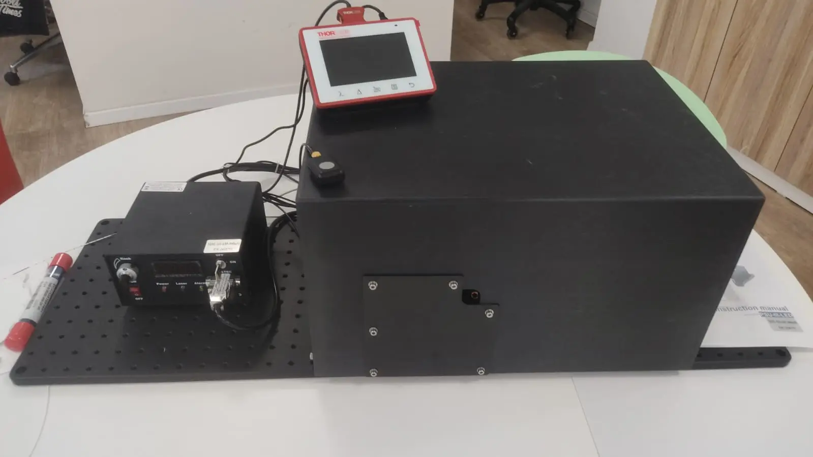
In production the same method is automated. The IZAK fiber transmission tester measures the laser through the fiber and through a bypass path, so every fiber is compared with the laser itself; for medical lasers this is how the delivered fluence is verified before a fiber ships. When several fibers or channels must be measured at once, a multi-channel power meter for high-power lasers records them in parallel.
Common mistakes that cost coupling efficiency
The launch works on day one and drifts out of the core when the laser warms up. Keep a 20–30% margin on both spot and NA.
Beam diameter and M² change with power and age. Measure them at the operating point.
The thin-lens spot exists only at the waist. A focus a few Rayleigh ranges in front of or behind the face makes a larger spot.
A single particle at high power can burn into the face. Inspect before every high-power test.
Part of the output cone misses the detector and transmission looks low. Move the detector closer or use a larger area.
Short test fibers carry cladding light to the detector. Strip it, or the launch looks better than it is.
IZAK products for this application
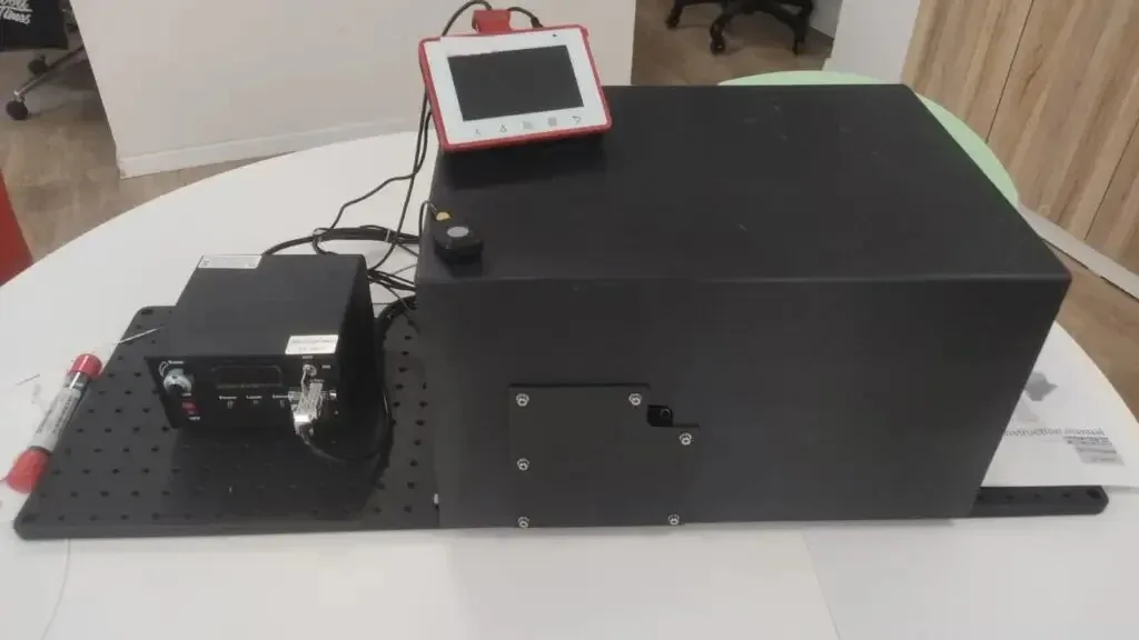 Fiber testFiber Transmission TesterFiber path and bypass reference path with calibrated high-power detectors.View product →
 Power measurementMulti-Channel Power MeterFive fiber-coupled SMA channels, 200 nm to 20 µm, up to 50 W per channel.View product →
 InspectionFiber Ferrule Inspection SystemDefects and cleanness, center offset, adhesive symmetry and transmittance tests.View product →
Need a launch, coupling or sampling design for your own instrument? See IZAK fiber optic design.
Frequently asked questions
QWhat is a good fiber coupling efficiency?
QHow large should the laser spot be compared with the fiber core?
QHow do you measure fiber transmission at high power?
References
- ISO 11146-1:2021, Lasers and laser-related equipment — Test methods for laser beam widths, divergence angles and beam propagation ratios — Part 1.
- IEC 61300-3-35, Fibre optic interconnecting devices and passive components — Basic test and measurement procedures — Part 3-35: Examinations and measurements — Visual inspection of fibre optic connectors and fibre-stub transceivers.
- IEC 60793-1-40, Optical fibres — Part 1-40: Attenuation measurement methods.
Tzachi Sabati
CEO, IZAK Scientific
Physicist specializing in photonics and quantum technologies, with deep expertise in quantum sensors and advanced optical systems. Leads the Advanced Quantum Lab course at the Technion, bridging academic excellence with industry innovation. At IZAK Scientific, provides cutting-edge photonics-based solutions, developing customized inspection and sensing systems for R&D and production. Passionate about advancing quantum sensing applications and integrating novel technologies to meet industry needs.
