

In short
- Two ways to measure a beam. A camera-based profiler records the whole beam in two dimensions in every frame. A scanning-slit or knife-edge profiler moves an aperture across the beam and builds one-dimensional profiles from a single detector.
- The beam shape decides first. For multimode, top-hat, elliptical or multi-spot beams you need the 2D image. A slit reports projections, and different beams can give identical projections.
- Spot size and pulses decide next. A camera needs about 10 pixels across the beam; a slit needs a slit narrower than 12% of the beam and, for pulsed lasers, at least 10 pulses in each crossing.
- Check your own case. The tool below takes the beam diameter, the camera pixel and the laser timing and tells you which instrument fits, and what to add if neither fits as is.
How each profiler builds a profile
A camera-based laser beam profiler places a pixel array in the beam. Every frame is a full two-dimensional intensity map, so the software can compute centroid, second-moment widths along the principal axes, ellipticity, orientation, uniformity and the shape of any structure in the beam. One frame is one complete measurement.
A scanning profiler uses one detector behind a moving aperture. With a slit, the detector signal versus slit position is the beam integrated along the slit direction: a one-dimensional projection. With a knife edge, the signal is the running integral of that projection, and the width is read between two clip levels (for example 10% and 90%). Two slits at 90° give two projections, usually called X and Y.
ISO 11146 defines beam widths from the second moments of the two-dimensional power density distribution. Its technical report ISO/TR 11146-3 describes the moving slit, the moving knife edge and the variable aperture as alternative methods for stigmatic and simple astigmatic beams, for cases where an array detector is not available or not suitable, provided the results are comparable. In practice this means: near-Gaussian, round or aligned beams. The further the beam is from that, the more the 2D image matters.
Camera or scanning slit: side by side
| Camera-based profiler | Scanning slit / knife edge | |
|---|---|---|
| What it records | Full 2D image in every frame | 1D projections along two or more axes |
| Beam shapes | Any: Gaussian, elliptical, multimode, top-hat, several spots | Best for near-Gaussian beams aligned with the scan axes |
| ISO 11146 widths | Direct, from 2D second moments, along the principal axes | Alternative method; comparable for simple beams |
| Smallest beam | About 10 pixels across; smaller with magnifying optics | A few microns, set by the slit width |
| Largest beam | About 80% of the sensor width; larger with reducing optics or a screen | Set by the aperture and scan length |
| Pulsed lasers | Single pulse, with a global shutter and a trigger | Needs many pulses in each slit crossing |
| Power density | Low saturation level; attenuation almost always needed | Only the light through the slit reaches the detector; the slit material sets the limit |
| Dynamic range in one scan | Set by the camera bit depth and noise | High, from a single detector |
| Moving parts | None | Rotating drum or translation stage |
| Typical use | R&D, alignment, pulsed and shaped beams, production test with pass/fail limits | Small focused CW spots, high power density, near-Gaussian beams |
Neither instrument is better in general. The rest of this page puts numbers on the three questions that usually decide: how small the spot is, how the laser is pulsed and how far the beam is from Gaussian.
Camera or scanning slit? Check your beam
Enter the beam diameter at the measurement plane, the laser timing and the beam shape. The check compares the beam with the camera pixels and sensor width, and with the slit width and the pulses a slit would catch in one crossing.
Camera and slit details
Model: camera fit = at least 10 pixels across the 1/e² diameter and the beam inside 80% of the sensor width. Slit-width error = growth of the second-moment width of a Gaussian beam convolved with a slit of width s: √(1 + 4s²/3D²) − 1. Pulses per crossing = repetition rate × D ÷ slit speed; 10 pulses is a working minimum and about 15 gives roughly 2% accuracy. Take the slit width and slit speed from the scanner’s data; for a rotating drum, the speed is about π × drum diameter × rotation rate, corrected for the slit angle. The camera list shows four of our UV–VIS–NIR models; SWIR, MWIR and LWIR models have larger pixels.
Small focused spots: pixels versus slit width
A camera resolves a beam well when about 10 or more pixels span the 1/e² diameter. With 3.45 µm pixels that is a beam of about 35 µm; with 2.5 µm pixels, about 25 µm. Below that the second-moment width is dominated by pixel sampling and the noise of a few bright pixels, and the result is no longer reliable. For a focused spot of 20 µm on 3.45 µm pixels (about 6 pixels), magnifying the focal plane about 2× onto the sensor with a relay lens restores the 10-pixel condition, at the cost of a smaller field of view. More on this trade-off in small vs large pixels in laser beam profiling.
A slit has its own resolution limit: the measured profile is the beam convolved with the slit. For a Gaussian beam the second-moment width grows by √(1 + 4s²/3D²), where s is the slit width and D the 1/e² diameter:
| Slit width / beam diameter | Width error | Example: 20 µm beam |
|---|---|---|
| 5% | +0.17% | 1 µm slit |
| 10% | +0.66% | 2 µm slit |
| 12.3% | +1.0% | 2.5 µm slit |
| 20% | +2.6% | 4 µm slit |
| 30% | +5.8% | 6 µm slit |
| 50% | +15% | 10 µm slit |
Second-moment width of a Gaussian convolved with a rectangular slit; the error can be removed by deconvolution only when the beam is known to be Gaussian.
So the rule of thumb is a slit narrower than about one eighth of the beam diameter. Microns-wide slits are what make scanning profilers attractive for tight CW focal spots. Knife-edge widths need a conversion to compare with D4σ or 1/e² (for a Gaussian, the 10/90 width × 1.561 gives the 1/e² diameter), see beam width definitions.
Pulsed lasers: pulses per slit crossing
A scanning slit samples the beam only when a pulse arrives. The profile is drawn from the pulses that fall inside the time the slit takes to cross the beam: N = repetition rate × D ÷ slit speed. About 8 to 10 pulses per crossing is a working minimum, and about 15 gives roughly 2% accuracy on the width.
The numbers grow quickly for small beams. At a slit speed of 0.1 m/s, a 200 µm beam is crossed in 2 ms: 2 pulses at 1 kHz, 20 at 10 kHz. A 50 µm focus is crossed in 0.5 ms: 5 pulses at 10 kHz, and 15 pulses need 30 kHz. Low-repetition lasers (Q-switched at 10–100 Hz, or single shots) are outside what a scanning slit can measure; pulse-to-pulse changes also appear as noise on the profile, because each point belongs to a different pulse.
A camera with a global shutter captures the whole beam of one pulse when the exposure is triggered by the laser. Every frame shows one pulse (or a known number of pulses), so you can see pulse-to-pulse changes in width, pointing and shape. The trigger modes, exposure settings and capture planning are covered in pulsed laser beam profiling.
Non-Gaussian beams: what projections hide
A projection adds up the beam along one direction, so information is lost. Three common cases show how much:
An elliptical beam with a 2:1 aspect ratio, rotated 45° to the scan axes, gives two projections of exactly the same width. The slit reports a round beam (ellipticity 1.0) when the true ellipticity is 0.5. At 22.5° it reports 0.64. A camera computes the principal axes and their angle from the 2D moments.
A hot spot, a ring, a dip in a top-hat or a weak second spot is averaged along the slit. Two beams that look very different on a camera can give the same X and Y projections.
Flatness and edge steepness of shaped beams (ISO 13694) need the power density at each point, not along lines. See verifying top-hat beams with beam profiling.
If the beam is multimode, shaped, astigmatic and rotated, or made of several beams, choose a camera even if the spot is small, and add magnifying optics. The same applies to M² measurements of such beams: ISO 11146 needs the widths along the principal axes at every plane, see the M² measurement guide.
Power, wavelength and attenuation
The slit itself is an attenuator: only a thin line of the beam reaches the detector, so a scanning profiler often accepts a focused beam with little or no filtering, up to the damage limit of the slit material. A camera pixel saturates at a fluence of tens of nJ/cm², so a camera profiler almost always works behind an attenuator or a beam sampler. That is a design step, not an obstacle: the beam profiler attenuation guide sizes the optical density for your power and beam.
Both instruments need a detector that responds at the wavelength. Camera-based profilers cover UV to long-wave infrared in separate families (300–1100 nm, SWIR up to 2.05 µm, MWIR 1.5–5.7 µm and LWIR 7.7–12 µm), so the wavelength picks the family before the slit-or-camera question comes up.
Production lines and integration
On a production line or inside an instrument, the questions change: no moving parts, a fixed field of view, a measurement in every frame and a pass/fail decision that an operator can read. A camera profiler gives all four. A board-level camera profiler can also be built into the customer’s own system or test station, with the attenuation designed for that beam path. A scanning profiler fits better as a lab tool for a known near-Gaussian focus.
IZAK products for this application
IZAK laser beam profilers are camera-based. We configure the sensor, the optics in front of it (attenuation, magnification or reduction) and the software for your beam.
 Beam profiling · 300–1100 nmUV–VIS–NIR Laser Beam ProfilersEight models with pixels from 2.5 to 4.8 µm and active widths from 3.7 to 26 mm, for small focal spots and large beams.View product →
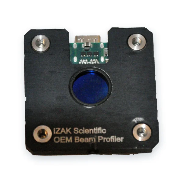 OEM · board levelOEM Board-Level Laser Beam ProfilersCompact global-shutter profilers for integration in your system or production station.View product →
 Laser acceptance testingTriBeam PrecisionBeam profile, power or energy and temporal pulse shape in one set-up.View product →
Other wavelengths: SWIR up to 2.05 µm, MWIR 1.5–5.7 µm and LWIR 7.7–12 µm. Still choosing? Read how to choose a laser beam profiler or the complete guide to laser beam profiling.
What to send us for a recommendation
With these details an engineer can tell you whether a camera profiler fits as is, or which optics it needs:
- Laser type and wavelengthe.g. fiber laser, 1070 nm
- Beam diameter at the measurement planeand whether you must measure at a focus
- CW or pulsedpulse energy, pulse width and repetition rate; single-shot or averaged
- Power or pulse energyfor the attenuation design
- Beam shapeGaussian, multimode, top-hat, several beams
- Where it will be usedlab bench, OEM integration or production line
Frequently asked questions
QWhat is the difference between a camera beam profiler and a scanning slit profiler?
QWhat is the smallest beam a camera beam profiler can measure?
QHow narrow should the slit be?
QCan a scanning slit profiler measure pulsed lasers?
QWhy does a scanning slit report a rotated elliptical beam as round?
QDo camera beam profilers need attenuation?
References
- ISO 11146-1: Lasers and laser-related equipment — Test methods for laser beam widths, divergence angles and beam propagation ratios — Part 1: Stigmatic and simple astigmatic beams.
- ISO/TR 11146-3: Lasers and laser-related equipment — Test methods for laser beam widths, divergence angles and beam propagation ratios — Part 3: Intrinsic and geometrical laser beam classification, propagation and details of test methods.
- ISO 13694: Optics and optical instruments — Lasers and laser-related equipment — Test methods for laser beam power (energy) density distribution.
Tzachi Sabati
CEO, IZAK Scientific
Physicist specializing in photonics and quantum technologies, with deep expertise in quantum sensors and advanced optical systems. Leads the Advanced Quantum Lab course at the Technion, bridging academic excellence with industry innovation. At IZAK Scientific, provides cutting-edge photonics-based solutions, developing customized inspection and sensing systems for R&D and production. Passionate about advancing quantum sensing applications and integrating novel technologies to meet industry needs.
