

In short
- Flash lamp lifetime is set by how close each pulse comes to the explosion energy. For a xenon lamp the single-shot explosion energy is Eₓ = Ke·√T, and the expected life is about (E₀/Eₓ)−8.5 flashes.
- Small changes pay off a lot. 10 % less energy per pulse gives about 2.5 times the life; doubling the pulse duration at the same energy gives about 19 times the life.
- Below about 20 % of Eₓ the lamp is no longer explosion-limited. Life then depends on electrode wear, wall ablation, peak current density and cooling.
- Design the driver around the lamp. The lamp impedance K₀, a critically damped pulse-forming network (α ≈ 0.8) and the wall loading in W/cm² decide C, L, the charge voltage and the cooling. The calculator below does all three.
What limits xenon flash lamp lifetime
A xenon flash lamp is a quartz tube with an electrode at each end, filled with xenon at a few hundred torr. A capacitor discharges through the gas in tens to thousands of microseconds, and the plasma radiates a broadband spectrum from the UV to the near-IR. That makes flash lamps the source of choice for pumping solid-state lasers, UV–VIS spectroscopy, photolysis, curing, sintering and pulsed UV treatment. It also means every flash puts a thermal and acoustic shock into the envelope.
Lamps reach end of life in a few distinct ways, and a good design knows which one it is fighting:
- Envelope fracture (explosion). The rapid plasma expansion creates a pressure and thermal shock at the inner wall. Close to the single-shot explosion energy the tube cracks in a few flashes; well below it the tube survives millions of flashes.
- Wall ablation. At high current density the plasma evaporates quartz from the bore. The deposit darkens the tube, reduces the output and changes the spectrum.
- Electrode wear. Sputtering of the cathode, especially at high peak current and with cold starts, coats the tube ends and makes triggering harder.
- Thermal overload. Too much average power overheats the envelope and the seals. A seal that stays hot for long periods fails even if every single pulse is gentle.
- Gas contamination. Overloaded walls release oxygen and other gases into the fill, which raises the trigger voltage and causes misfires.
The first mechanism dominates at high energy per pulse, the others at high average power or long life. The rest of this note shows how to put numbers on each.
Explosion energy: the single-shot limit
The explosion energy Eₓ is the electrical energy per pulse that cracks the envelope in a single flash. It grows with the bore and arc dimensions and with the square root of the pulse duration:
Eₓ = Ke · √T, with Ke = Q · l · d
- l is the arc length and d the bore diameter, both in cm.
- T is the circuit time constant √(LC) in seconds. For a critically damped discharge it is about one third of the full pulse width measured between the 10 % current points.
- Q depends on the envelope. For clear fused quartz with bores up to 8 mm a commonly used value is about 2.46 × 10⁴ W·s½/cm², falling to about 2.1 × 10⁴ for 10–12 mm bores and 2.0 × 10⁴ above that. Doped or thin-walled envelopes differ, so use the constant the lamp maker gives for the exact tube when you have it.
The square root of T is the key design lever. A longer pulse spreads the same energy over more time, the shock is weaker and Eₓ rises. A short, punchy pulse is what many applications want, and it is exactly what costs lamp life.
The flash lamp lifetime law
When the energy per pulse is a large fraction of Eₓ, the expected number of flashes follows a steep power law:
N ≈ (E₀ / Eₓ)−8.5
where E₀ = ½·C·V₀² is the energy stored in the capacitor and delivered to the lamp. The exponent makes the lifetime very sensitive to loading:
| E₀ / Eₓ | Expected life (flashes) | Typical use |
|---|---|---|
| 58 % | ≈ 1 × 10² | Single-shot or test pulses only |
| 44 % | ≈ 1 × 10³ | High-energy research lasers |
| 33 % | ≈ 1 × 10⁴ | Heavily loaded pump lamps |
| 26 % | ≈ 1 × 10⁵ | Moderately loaded lasers |
| 20 % | ≈ 1 × 10⁶ | Knee of the curve; other wear mechanisms take over |
Two rules of thumb follow directly. Cutting the energy per pulse by 10 % multiplies the life by 0.9−8.5 ≈ 2.5. Doubling the pulse duration at the same energy raises Eₓ by √2 and multiplies the life by (√2)8.5 ≈ 19.
The law describes the explosion-limited regime only. Below roughly 20 % of Eₓ it predicts lives of 10⁷, 10¹⁰ and beyond, which no real lamp reaches: the electrodes, the wall and the seals wear out first. In that regime, plan for 10⁶ flashes or more (lightly loaded lamps can pass 10⁸) and control the peak current density and average power instead. When the lamp sits close to a reflector or inside a laser cavity, the returned radiation heats the wall further; derating the energy by 10–30 % is common practice there.
Designing the pulse-forming network
A flash lamp is a nonlinear load. Once the discharge fills the bore, its voltage follows V = K₀ · √I, where the impedance parameter K₀ (in Ω·A½) depends on the geometry and the fill pressure. For xenon:
K₀ = 1.28 · (P / 450)0.2 · l / d
with P the cold fill pressure in torr and l/d the ratio of arc length to bore. A 5 mm bore lamp with a 50 mm arc at 450 torr has K₀ = 12.8 Ω·A½.
The simplest driver is a single-mesh network: a capacitor C charged to V₀, an inductor L that shapes the pulse, and the lamp. The damping parameter α = K₀ / √(V₀ · Z₀), with Z₀ = √(L/C), sets the pulse shape. α ≈ 0.8 gives a critically damped pulse: a single current lobe with no reversal, which is what the lamp and the capacitor like best; the practical window is about 0.7 to 1.1. Below it the current rings, above it the pulse becomes long and inefficient.
For a target energy E₀, time constant T and α = 0.8 the component values follow from three equations:
| Quantity | Design equation |
|---|---|
| Capacitance | C = (2 · E₀ · α⁴ · T² / K₀⁴)1/3 |
| Inductance | L = T² / C |
| Charge voltage | V₀ = √(2 · E₀ / C) |
For the critically damped case our circuit simulation gives a peak current of about 0.5 · V₀ / Z₀, a full width of about 3.1 T between the 10 % points and about 2.5 T at one third of the peak. The peak current divided by the bore area is the peak current density. It controls both the spectrum and the wall ablation: beyond roughly 7 kA/cm² ablation becomes significant, and lamps for long life usually run well below that.
Two practical points complete the driver. The lamp must be triggered: an external trigger winding or wire is the cheapest, a series trigger transformer is more reliable in a closed cavity, and a simmer supply that keeps a low-current discharge alive between pulses reduces jitter and electrode wear at higher repetition rates. And the charge voltage must stay above the lamp’s minimum self-flash voltage for the chosen trigger, or the lamp will misfire.
Average power and wall loading
The explosion law protects the lamp against single pulses. The average power protects it against heat. Divide the average electrical power by the inner wall area of the arc region:
Wall loading = E₀ · f / (π · d · l) in W/cm²
| Wall loading | Cooling |
|---|---|
| Below about 15 W/cm² | Natural convection in open air |
| 15–30 W/cm² | Forced air; consider liquid cooling at the low end if the lamp is enclosed in a cavity |
| 30–200 W/cm² | Liquid cooling with a flow tube |
| Above about 200 W/cm² | Beyond the usual rating of a 1 mm clear quartz wall; needs a special envelope |
UV-absorbing doped quartz has a lower rating than clear fused quartz, and krypton lamps are usually derated by about 10 % compared with xenon. Keep the seals cool as well: long periods near 200 °C at the electrode seals shorten the life even when the wall loading is in range.
Worked example: a 5 mm × 50 mm pump lamp
A xenon lamp with a 5 mm bore, a 50 mm arc and 450 torr fill must deliver 150 J per pulse at 1 Hz. The first design uses T = 50 µs.
- K₀ = 1.28 × 1 × 50 / 5 = 12.8 Ω·A½.
- Eₓ = 2.46 × 10⁴ × 5 cm × 0.5 cm × √(50 × 10⁻⁶ s) = 435 J. E₀/Eₓ = 34.5 %.
- Life ≈ 0.345−8.5 ≈ 8.5 × 10³ flashes. At 1 Hz that is under three hours of operation.
- Network for α = 0.8: C = 225 µF, L = 11.1 µH, V₀ = 1154 V. Peak current about 2.6 kA, or 13 kA/cm² in the bore.
- Wall loading: 150 W / (π × 0.5 × 5) cm² = 19 W/cm², so forced air.
The life is far too short, and the current density is high. Two changes fix it:
| Design | E₀ | T | Eₓ | E₀/Eₓ | Life (flashes) | C / L / V₀ | Peak current density |
|---|---|---|---|---|---|---|---|
| A: short pulse | 150 J | 50 µs | 435 J | 34.5 % | 8.5 × 10³ | 225 µF / 11.1 µH / 1154 V | 13.1 kA/cm² |
| B: longer pulse | 150 J | 100 µs | 615 J | 24.4 % | 1.6 × 10⁵ | 358 µF / 28.0 µH / 916 V | 8.3 kA/cm² |
| C: longer pulse, 120 J | 120 J | 100 µs | 615 J | 19.5 % | > 10⁶ (not explosion-limited) | 332 µF / 30.1 µH / 850 V | 7.1 kA/cm² |
Doubling T alone buys a factor of 19. Accepting 20 % less energy, for example by improving the coupling optics instead of pushing the lamp, takes the design past the knee of the curve. From there, the remaining work is cooling (15 W/cm², forced air) and keeping the current density in check.
Flash lamp lifetime and driver calculator
Design mode sizes a critically damped network (α = 0.8) for your energy and pulse time. Check mode takes your existing C, V₀ and L. Both give the explosion energy, the expected life, the peak current density, the wall loading and a simulated current pulse.
Xenon fill, clear fused quartz envelope. Eₓ uses Q = 2.46 × 10⁴ (bore ≤ 8 mm), 2.1 × 10⁴ (up to 12.5 mm) or 2.0 × 10⁴ W·s½/cm². Estimates for design planning; the lamp maker’s ratings take precedence.
Spectrum, current density and the envelope
The pulse design also sets the colour of the light. At low current density a xenon discharge radiates much of its energy in strong line groups in the near-IR, roughly between 800 and 1000 nm. As the current density rises, the continuum grows and the output shifts toward the blue and the UV. A short, high-current pulse is therefore richer in UV than a long, gentle one at the same energy, which matters for spectroscopy, photochemistry and pulsed UV treatment, and also for the solarization of nearby optics.
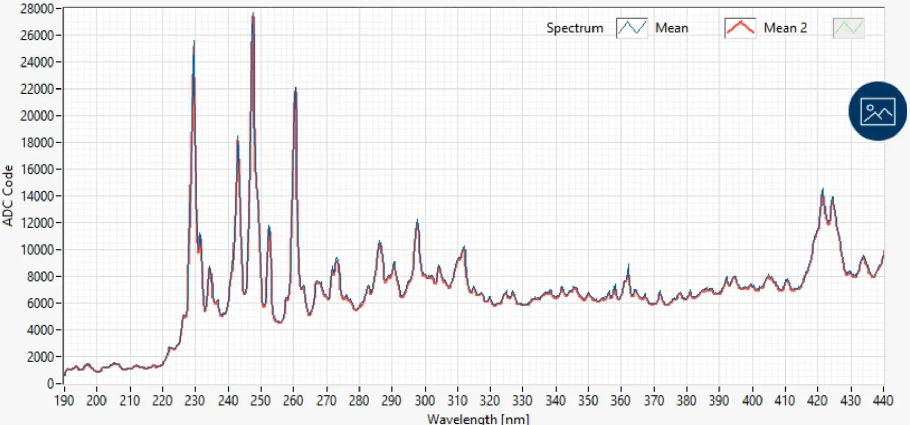
The envelope filters the result. Clear fused quartz passes the deep UV and suits UV–VIS spectroscopy and UV processes. UV-absorbing doped quartz removes the short-wave UV, which prevents ozone and protects laser rods and plastics, at the cost of a lower wall-loading rating. Choose the envelope for the band you need, then design the pulse for the life you need. For an overview of where pulsed xenon fits, see xenon flash lamps in classical and quantum applications and applications for the pulsed flash lamp; for UV treatment, pulsed versus continuous UV compares the two approaches.
Common flash lamp design mistakes
Using the full pulse width as TEₓ off by √3
The explosion formula uses T = √(LC), about one third of the full pulse width. Entering the full 10 % width, about 3.1 T, makes Eₓ look about 1.8 times larger and the life prediction more than 100 times too optimistic.
Designing to the energy, not the current densitywall ablation
Two designs with the same E₀ and life prediction can differ by a factor of two in peak current density. The one with the higher density ablates the wall faster, darkens sooner and shifts the spectrum. Check the peak current divided by the bore area, not only E₀/Eₓ.
Ignoring the average powerrepetition rate
A pulse at 10 % of Eₓ is safe once, but at 20 Hz it can overheat a lamp rated for convection cooling. Compute the wall loading for the highest repetition rate the product will ever run, and size the cooling for it.
An under-damped networkα below 0.7
With too little inductance or too high a voltage the current rings. Reversal stresses the electrodes and the capacitor, and the residual charge can re-trigger the lamp. Adjust L or V₀ to bring α near 0.8.
Skipping the measurementverification
Lamp dimensions, actual fill pressure and stray inductance in the wiring all shift the real pulse from the design. Record the current pulse with a current probe and measure the optical output and its spectrum at the start of life, so you can see drift before the lamp fails.
IZAK products for this application
When you need a pulsed broadband source that is ready to integrate, or a lamp, driver and control electronics built around your specification, these are the starting points.
 UV–VIS–IR light sourcePXL Scientific Pulsed Xenon Lamp Module500–850 V in 8 steps, 0.2–2 Hz or single pulse, up to a few J per pulse, 12 VDC; standalone, USB or analog control.View product →
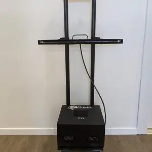 Pulsed UVPXL SanitizerCompact pulsed UV light unit for surface disinfection.View product →
Most electronic, mechanical and optical parameters of the lamp module can be customized. For a complete source, driver or test system, see custom electro-optical system design.
Frequently asked questions
QHow long does a xenon flash lamp last?
QHow do you calculate flash lamp explosion energy?
QWhat is critical damping in a flash lamp circuit?
Tzachi Sabati
CEO, IZAK Scientific
Physicist specializing in photonics and quantum technologies, with deep expertise in quantum sensors and advanced optical systems. Leads the Advanced Quantum Lab course at the Technion, bridging academic excellence with industry innovation. At IZAK Scientific, provides cutting-edge photonics-based solutions, developing customized inspection and sensing systems for R&D and production. Passionate about advancing quantum sensing applications and integrating novel technologies to meet industry needs.
