

In short
- Use a global-shutter sensor. All pixels expose at the same moment, so a short pulse lands on the whole image. Rolling-shutter sensors suit CW lasers only.
- Decide how many pulses each frame should hold. One pulse per frame needs a trigger. Ten or more pulses per frame give a stable, averaged beam without one.
- Plan attenuation from the pulse, not the average power. Energy per frame sets saturation; peak fluence and peak power set damage, on the sensor and on the filters.
- Subtract the background and report statistics. Take a dark frame with the same exposure, then report mean and spread over many pulses.
Why pulsed beams need a different set-up
A camera-based profiler integrates light for as long as the exposure lasts. With a CW laser the signal is steady, so any exposure gives the same picture. A pulsed laser delivers its energy in bursts that last nanoseconds, picoseconds or femtoseconds, separated by long gaps. What the camera records then depends on three timing questions: does the exposure contain a pulse, how many pulses does it contain, and do all pixels see the same pulse.
The answers decide whether the profile is a true picture of the beam or a measurement artefact: half-images, frames that flicker from bright to dark, or a saturated core that hides the real width. The rest of this article explains how to set the shutter, the trigger, the exposure and the attenuation so the profile is right, and includes a free planner for your own laser. For the basics of beam profiling, start with The Complete Guide to Laser Beam Profiling.
Global shutter or rolling shutter
In a global-shutter sensor every pixel starts and stops integrating at the same time. In a rolling-shutter sensor the rows are exposed one after the other, so the top of the image is recorded earlier than the bottom. With a CW laser this makes no difference. With a pulse that lasts a few nanoseconds it does: only the rows that are integrating at that moment see the pulse.
| Global shutter | Rolling shutter | |
|---|---|---|
| Exposure | All rows at once | Row by row, offset in time |
| A single short pulse | Recorded on the whole image | Recorded only on the rows exposed at that moment: a band, a cut beam or nothing |
| Many pulses per frame | Correct averaged profile | Usable only when every row sees many pulses; residual stripes are common |
| Trigger | Frame can be synchronised with the laser | The pulse still meets one band of rows |
| Use it for | Pulsed and CW lasers | CW lasers only |
If the laser is pulsed, or might be modulated, choose a global-shutter profiler. The lower-cost rolling-shutter models are the right choice only for CW beams.
Trigger, exposure and pulses per frame
The repetition rate of the laser and the exposure of the camera set how many pulses each frame contains. Multiply them: pulses per exposure = repetition rate × exposure time. A 1 kHz laser and a 5 ms exposure give five pulses per frame. Three working modes follow from that number.
For low repetition rates and for checking every pulse. The camera is triggered by the laser, and the exposure is longer than the pulse plus the trigger delay and jitter, but shorter than the gap to the next pulse.
For kHz to MHz lasers. With ten or more pulses in each exposure, the count changes by at most 10% from frame to frame, and the image is a stable average beam. No trigger is needed.
With one to ten pulses per frame and no trigger, each frame holds a different number of pulses, so the brightness jumps by 10% to 100%. Trigger the camera, or lengthen the exposure until each frame holds at least ten pulses.
Where the trigger comes from
- The laser sync output. Most pulsed lasers and their drivers provide an electrical trigger that comes before or with the optical pulse. Use it whenever it exists; set the camera delay so the exposure window brackets the pulse.
- A fast photodiode on a pick-off. When the laser has no sync output, a small reflection onto a photodiode can produce the trigger. The delay is then fixed by cable and electronics, so the exposure must open early enough or the trigger must be taken from the previous pulse.
- Software trigger. Useful for single-shot tests on demand, for example in a production station, when the exposure is long enough to contain the pulse with margin.
A frame rate below the repetition rate is not an error. A 30 frames-per-second camera on a 1 kHz laser records one pulse in about every 33. For a stable laser that is enough to build pulse-to-pulse statistics; to record every pulse you need a frame rate at least as high as the repetition rate, often reached with a smaller region of interest.
Pulsed-laser capture planner
Enter your laser and camera settings. The planner gives the pulses per exposure, the peak power, fluence and intensity at the sensor plane, and whether your trigger and exposure settings will give single-pulse or averaged frames. It assumes a Gaussian beam and a Gaussian pulse.
Energy, peak power and attenuation
A camera sensor needs only a tiny part of the beam. Almost every pulsed set-up needs sampling, attenuation or both, and two different limits apply.
- Saturation is set by the energy per frame. The pixels integrate everything that arrives during the exposure, so what matters is the energy density per frame on the sensor: one pulse in single-shot mode, or all the pulses in the exposure in averaged mode. Keep the peak pixel below full scale with some margin; a saturated core flattens the profile and makes every width wrong.
- Damage is set by the pulse. Peak fluence (energy per area in one pulse) and peak intensity (peak power per area) decide whether the sensor or a filter is damaged. A 1 mJ, 10 ns pulse in a 2 mm beam carries only 1 W of average power at 1 kHz, but its peak fluence is about 64 mJ/cm² and its peak intensity about 6 MW/cm². Shorter pulses with the same energy raise the peak intensity in proportion.
For a Gaussian beam the peak fluence is F₀ = 2E / (πw²), where E is the pulse energy and w the 1/e² radius. For a Gaussian pulse the peak power is about 0.94 E / τ, where τ is the pulse width (FWHM). The planner above uses these relations.
A safe attenuation order
- Sample first. Take a small reflection from an uncoated wedge or a beam sampler, so most of the energy goes to a beam dump. The sample carries a few percent of the beam and keeps its shape when the optics are of good quality.
- Then reflect. Reflective attenuators handle the higher fluence in front of the chain; absorbing filters can heat, lens or crack under strong pulses.
- Fine-tune last. Use absorbing neutral-density filters close to the sensor, where the fluence is already low.
- Check for distortion. Rotate or swap one attenuator and compare the profiles. A real beam does not change; ghosts, fringes and thermal lensing do.
Ultrashort pulses add one more limit. At femtosecond durations the peak intensity can trigger nonlinear effects inside thick filters and windows, which change the beam before it reaches the sensor. Keep the energy low before any transmissive optic and prefer reflective sampling for fs lasers.
Background, baseline and noise
Second-moment widths (D4σ), the reference widths of ISO 11146, weigh the wings of the beam heavily. A small offset spread over thousands of pixels can add more to the result than the beam itself. Pulsed measurements are more exposed to this, because the beam is present for nanoseconds while the sensor collects noise and stray light for the whole exposure.
- Take a dark frame with the laser blocked, at the same exposure, gain and temperature, and subtract it.
- Keep the exposure short when triggering: a window just wider than the pulse plus jitter collects less ambient light and dark signal.
- Limit the integration area to about three times the beam width, as ISO 11146 recommends, so distant noise does not inflate the width.
- Average frames, not pulses, when you need a clean shape. Averaging N triggered frames reduces random noise by about √N while keeping single-pulse timing.
Pulse-to-pulse statistics
Pulsed lasers rarely repeat perfectly. Thermal effects, pump fluctuations and mode competition move the centroid and change the width from pulse to pulse, and the first pulses of a burst often differ from the rest. Single-shot capture makes these changes visible:
- Pointing stability: the spread of the centroid over many pulses, often reported as a standard deviation in µm or µrad after a lens.
- Width and ellipticity stability: mean and spread of the beam diameter on both axes.
- Relative energy: the total counts in the frame track the pulse energy, which is useful for spotting missing or weak pulses.
- First-pulse behaviour: trigger on the start of a burst to see how the beam settles.
Report the number of pulses and the capture mode with every result. A width averaged over 100 pulses and a single-pulse width are different measurements. In production, pass/fail limits on these statistics catch drift before it reaches the customer.
Pulsed lasers in the infrared
The same rules apply beyond 1.1 µm, with a few differences by band:
- SWIR, up to 2.05 µm: eye-safe and fiber lasers at 1.5 µm and 2 µm are often pulsed. Use triggered capture for low repetition rates and averaged frames for high ones, as in the visible.
- MWIR, 1.5–5.7 µm: for ns and fs sources the frame is triggered from the laser and the exposure collects whole pulses. Fast frame rates let you see pulse-to-pulse pointing and shape changes, not only the average.
- LWIR, 7.7–12 µm: many CO₂ lasers are power-controlled by fast pulse modulation, so each frame integrates many pulses and shows the working beam as the process sees it. For low repetition rates, capture can be triggered from the laser to follow individual pulses.
See the SWIR, MWIR and LWIR profiler families for the models in each band.
Checklist: profiling a pulsed laser
- Global shutterconfirm the profiler model is global shutter
- Pulses per framerepetition rate × exposure: 1 with a trigger, or 10 and more without
- Trigger and delayexposure window brackets the pulse plus jitter
- Damage checkpeak fluence and peak intensity at every optic and at the sensor
- Saturation checkpeak pixel below full scale at the energy per frame
- Attenuation chainsample, reflect, then fine-tune; check for distortion
- Backgrounddark frame subtracted, integration area about three widths
- Statisticsnumber of pulses and capture mode stated with every result
Free PDF · 6 pages
Take the checklist with you
- Wavelength-to-detector map, 0.3 to 12 µm
- Pixel-pitch and sensor-size rules with worked examples
- Pulsed vs CW, attenuation and production QA checklists
- A fill-in specification worksheet for your RFQ
IZAK products for this application
Profilers and test systems for pulsed and CW lasers, from the lab bench to the production line.
 Beam profiling · 300–1100 nmUV–VIS–NIR Laser Beam ProfilersEight models from 1.2 to 67 MP, with hardware or software trigger and pass/fail tests.View product →
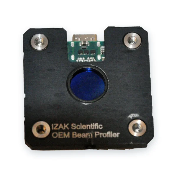 OEM · board levelOEM Board-Level Laser Beam ProfilersFour global-shutter models for pulsed and CW lasers, for integration in your system.View product →
 Laser acceptance testingTriBeam PrecisionBeam profile, power or energy and temporal pulse shape in one set-up.View product →
Need a pulsed-laser test station that is not in the catalog? We design custom electro-optical systems →
What to send us for a recommendation
With these details an engineer can recommend the profiler, trigger set-up and attenuation chain in one reply:
- Laser type and wavelengthe.g. Q-switched Nd:YAG, 1064 nm
- Pulse formatpulse width, energy and repetition rate, or burst pattern
- Triggeris there a sync output, and how far ahead of the pulse?
- Beam sizeat the planned measurement plane
- What you need to seeevery pulse, statistics or an averaged beam
- EnvironmentR&D bench, OEM integration or production line
Frequently asked questions
QCan a camera-based beam profiler measure a pulsed laser?
QWhy does my pulsed beam look cut or striped?
QWhy do my frames flicker between bright and dark?
QDo I need a trigger for a high-repetition-rate laser?
QHow do I attenuate a pulsed beam without damaging the sensor?
QDoes pulse width matter for the beam profile?
References
- ISO 11146-1: Lasers and laser-related equipment — Test methods for laser beam widths, divergence angles and beam propagation ratios — Part 1: Stigmatic and simple astigmatic beams.
- ISO 11146-2: Part 2: General astigmatic beams.
- ISO/TR 11146-3: Part 3: Intrinsic and geometrical laser beam classification, propagation and details of test methods.
- ISO 21254: Lasers and laser-related equipment — Test methods for laser-induced damage threshold.
Tzachi Sabati
CEO, IZAK Scientific
Physicist specializing in photonics and quantum technologies, with deep expertise in quantum sensors and advanced optical systems. Leads the Advanced Quantum Lab course at the Technion, bridging academic excellence with industry innovation. At IZAK Scientific, provides cutting-edge photonics-based solutions, developing customized inspection and sensing systems for R&D and production. Passionate about advancing quantum sensing applications and integrating novel technologies to meet industry needs.
