

Fiber optics inspection · Production test
Ferrule, cleave, transmission and connector-alignment testers, built for fiber production lines and for high-power laser delivery fibers.
IZAK Scientific designs and builds fiber optics inspection systems. For custom fiber production we measure fiber tip cleaving, fiber pitch and fiber height, and we built a system that measures and tests fiber bundles for communications research and manufacturing quality. For medical lasers that deliver high-power energy to tissue through optical fibers, we built two systems: one tests fiber transmission after production and before delivery, and one aligns fiber connectors with a beam profiler that images narrow high-power beams across 5–7 pixels inside SMA connectors.

See it in action
A short demonstration of the IZAK ferrule inspection system: the fiber end face is imaged under the microscope and the software checks fiber centering, adhesive symmetry and end-face defects.
Four fiber testers
Each system answers one production question. They can run on their own, or share one station, one software and one report format on your line.

01 · Ferrule inspection
The ferrule inspection tester is a key station in fiber production. It checks the quality and reliability of optical fiber ferrules before they become connectors, so a defect is found at the station and not in the field.
It combines microscope-based imaging with inspection software, or with an API when the inspection runs inside your own production software.
Applications: quality control in fiber production, process optimization, and research and development of new fiber types. Read: how the ferrule inspection system works
02 · Cleave inspection
The cleaving tester inspects the fiber after cleaving and uses image processing for precise measurements. It is built for high-volume production, where speed, accuracy and consistency decide the yield of every fiber connection.
The acceptance criteria are set to your specification: for example the end-face quality after the cleave and, in fiber arrays, the fiber pitch and fiber height shown above.
Post-cleave inspection with this system sets a consistent quality standard for fiber optic manufacturing.

In this short demonstration the IZAK image-processing application inspects a fiber array: it measures fiber pitch, fiber height, cleave angle and fiber angle, and lists every result against its limits with a pass/fail verdict.
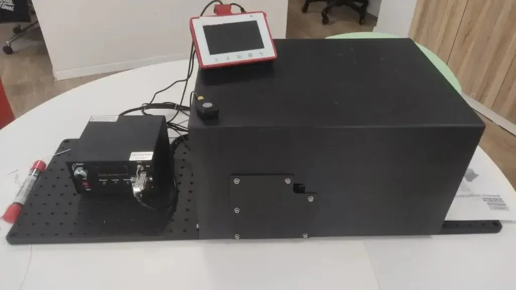
03 · High-power transmission
This tester measures how much high-power laser energy an optical fiber transmits. Every part of the optical path is designed for high power.
Its main purpose: the right fluence in medical laser devices. Fluence is the optical energy per unit area on the tissue. If the fiber transmits too little, the fluence drops and the treatment loses its effect. If it transmits more than the device is set for, the patient risks burns or tissue damage. Testing each fiber keeps the treatment both safe and effective.
Calibrated detectors that handle high laser power measure both paths, and the system calculates the transmission efficiency of the fiber from the two readings.
Calculator
Enter the two readings of a dual-path test. Add the pulse energy and spot size to see the fluence the fiber delivers to tissue, and compare it with the target.
Dual-path reading
Fluence at the tissue (optional)
Enter the readings.
Transmission = main ÷ bypass. Loss = −10·log₁₀(transmission). Fluence = delivered energy ÷ spot area, assuming a uniform (top-hat) spot. Check the result against your device’s own calibration and safety limits.
04 · Narrow-beam alignment
Our multi-channel power meter is engineered for precise measurement of high-power, narrow laser beams, with peak powers in the tens of kilowatts. A custom narrow-beam adapter probe profiles high-irradiance beams with diameters down to about 100 µm and images them across 5–7 pixels, enough to characterize beam width and distribution in research and industry.
Alignment and focus. The main use is aligning SMA connectors: a centered beam is essential for efficient coupling into the fiber. The same probe evaluates the focus on the surface or inside a fiber ferrule, which helps quality assurance, maintenance and troubleshooting.

From requirement to production line
Most fiber testers we deliver are adapted to one product and one line. The path is the same each time, and each step ends with something you can review.
Also from our production test line: LED Tester
FAQ
Our ferrule inspection tester checks four things in one station: symmetrical installation of the core adhesive inside the ferrule, defects and cleanliness of the end face, the offset of the fiber core from the ferrule center, and transmittance and losses. Separate IZAK systems inspect fibers after cleaving, measure high-power transmission and align SMA connectors.
Yes. The test parameters are customizable for different fiber types and standards, and the inspection can run from our software or through an API inside your own production software.
The tester has two optical paths. The main path sends the laser through the fiber under test, and the bypass path measures the same laser without the fiber as a reference. Calibrated high-power detectors read both, and the system calculates the transmission efficiency from the two readings.
The fiber decides how much energy reaches the tissue, and therefore the fluence. Too little transmission lowers the fluence and the treatment effect; too much risks burns or tissue damage. Testing every fiber before delivery keeps the treatment safe and effective.
Yes. A narrow-beam adapter probe on our multi-channel power meter profiles high-irradiance beams down to about 100 µm in diameter across 5–7 pixels. It is used to align SMA connectors and to check the focus on or inside a fiber ferrule.
Yes. We design the optics, mechanics and software, test the prototype on your samples, set pass/fail limits from your specification, add data logging and reports, and hand the station over to your line with operator training.
Send the fiber, the connector and what the station must prove. We reply with the questions that matter and a proposed approach.
