Optical system design services

Optical System Design, from Requirement to Production

Optics, opto-mechanics, prototype and test, designed to work on the bench and on the production line.

Optical system design is the process of planning, creating and optimizing systems that use light for a specific function. It ranges from simple lenses and mirrors to complex assemblies in cameras, telescopes, microscopes and fiber optic communication systems. Below are the ten elements of the work, each with an example from projects that IZAK Scientific conceived, designed, built and evaluated.

ISO 9001:2015UV to LWIROptics + opto-mechanicsPrototype and test
Optical components selected and tested by IZAK Scientific
Optical components selected and tested in our lab.

The method

Ten elements of an optical system design

The order matters: each step builds on the decisions of the one before, and each ends with something you can review.

  1. Objective identification
  2. Selection of optical components
  3. Light behaviour analysis
  4. Optical layout design
  5. Performance simulation and optimization
  6. Mechanical integration
  7. Prototyping and testing
  8. Manufacturing and assembly
  9. Application-specific considerations
  10. Compliance with standards

STEP 01 OF 10

Objective identification

Every design starts with what the system must do with light: focus it, form an image, disperse it into a spectrum, transmit information, or shape it in some other way. We write that purpose as numbers that a test can confirm: wavelength band, power or radiance, field of view, resolution, size, environment and cost.

Example from our projects

Coupling light into a spectrometer slit for spectral analysis. The light has to be directed and focused into a narrow slit, and how well that is done decides how accurate and efficient the whole analysis is.

What you get: A requirement sheet with acceptance criteria.

See the slit-coupling project

Relay optics coupling light into a spectrometer entrance slit
Coupling light into a spectrometer slit.

STEP 02 OF 10

Selection of optical components

The purpose decides the parts. Lenses, mirrors, prisms, gratings and optical fibers each have properties that contribute to the function of the system: focal length and aberrations, reflectance and coatings, dispersion, diffraction efficiency, numerical aperture and loss.

We choose each component against the requirement and against availability, cost and lead time. Where a catalogue part meets the specification we use it; custom optics are kept for the places where they make the difference.

What you get: A component trade study with the reason for each choice.

STEP 03 OF 10

Light behaviour analysis

A designer has to know how light will refract, reflect, diffract, be absorbed and disperse at every surface and in every material along the path. These effects set the efficiency, the image quality and the stray light of the final system.

Example from our projects

Delivering light through an optical fiber, with the focus on efficient coupling into the fiber. Coupling efficiency depends strongly on the numerical aperture of the light beam: the cone of the focused beam has to fit inside the acceptance cone of the fiber, and the focused spot has to fit inside the core. The same analysis covers the optical output from the fiber, fiber transmission and the related parameters.

What you get: Coupling and loss budget for each interface.

See the fiber coupling project

Examples of coupling, decoupling and sampling light from and to optical fiber
Coupling, decoupling and sampling light in fiber.

STEP 04 OF 10

Optical layout design

The layout decides how the components are arranged to achieve the result. It fixes the physical parameters: focal length, aperture size, field of view and the position of each element.

Example from our projects

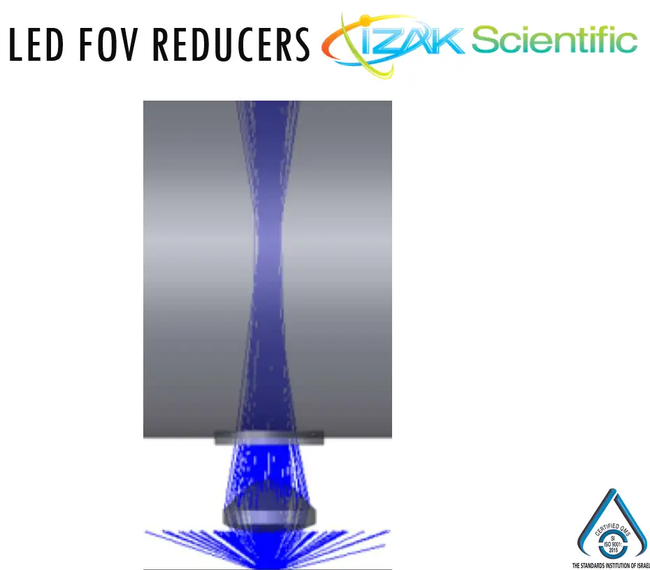
An LED field-of-view reducer: a low-cost way to use LEDs as light sources for optical analysis. The main challenge was to keep the bill of materials low while keeping the design robust. We developed a custom aspheric lens from scratch, matched to the optical properties of the chosen LED chip, for the best beam focus, depth of focus and maximum irradiance at the analysis position. The lens is molded to keep its cost low.

What you get: Optical layout with first-order parameters and a lens prescription.

See the LED optics project

LED field of view reducer with a custom molded aspheric lens
LED field-of-view reducer.

STEP 05 OF 10

Performance simulation and optimization

Optical design software lets us simulate the performance of the system, look at image quality, aberrations and light efficiency, and refine the design from the results.

This software is based mainly on geometrical optics and does not capture every aspect of an optical design. Simulation alone is not enough: practical considerations, physical effects that the model leaves out and real-world testing all have to be part of the work. Good design balances simulation with measurement.

QuestionSimulation answers itNeeds a measurement
Spot size and aberrationsYes, for the nominal designTo confirm the built system
ThroughputNominal coupling and vignettingReal coatings, scatter and contamination
Source behaviourOnly as well as the source modelReal angular spread and beam shape of the LED or laser
Stray lightPartly, with a full mechanical modelReflections from real mounts and edges
Assembly and alignmentThrough tolerance analysisEach built unit
TemperatureWith thermal data for every materialDrift over the real operating range

What you get: Simulation results and a list of what must be confirmed by measurement.

STEP 06 OF 10

Mechanical integration

The optics have to be housed in a mechanical structure that keeps them stable and aligned, and that takes precision. Real-world factors enter here: precision and tolerances, mass, thermal expansion, the change of refractive index with temperature (dn/dT) and chemical and environmental effects.

Tolerancing keeps a lens design practical and economical to manufacture. Loosening tolerances saves cost but can compromise optical performance, so the design has to find the balance. A tolerance analysis shows which errors matter most, so tight tolerances go only where they pay for themselves. We integrate the optical design into a 3D mechanical CAD model together with all system tolerances.

DecenterTiltAxial spacingSurface formThicknessWedgeRefractive indexThermal expansiondn/dT

What you get: Opto-mechanical 3D model and a tolerance table.

STEP 07 OF 10

Prototyping and testing

A prototype is built and tested to confirm that the system meets its specification, often with several rounds of adjustment. Each prototype needs a test procedure that proves it does what it was designed to do. Problems found early cost less time and money.

We build a prototype and test it at the earliest opportunity, using off-the-shelf components for a fast, working first version. We often propose a rapid prototype with the full opto-mechanical layout made from off-the-shelf parts, to prove feasibility before advanced development. Every iteration is measured with our own beam profilers, so a change in the layout shows up as a change in the measured profile.

Example from our projects

Laser systems that need uniform illumination. The right solution depends on the type of laser. Laser diodes have a fast axis and a slow axis because of diffraction at their emitting aperture, so their beam behaves differently from the beam of a solid-state or fiber laser.

What you get: A working prototype, a test procedure and measured results.

See the uniform illumination project

Uniform illumination produced from laser diodes
Uniform laser illumination prototype.

STEP 08 OF 10

Manufacturing and assembly

After a successful design and prototype, the system moves to production, and the precision of the prototype has to be kept. Variations between batches of mounts or optics cause tilt, decentering, axial spacing errors and similar problems. We advise customers to use test equipment on the line, so optical performance stays the same over years of production.

Example from our projects

A test jig that measures the output beam of a 10.6 µm CO₂ laser with coupling optics. Standard beam profilers were too expensive for this application, so we developed a beam profiler that can be adapted to any imager. In a second phase it was tailored for the customer with optics for the long-wave infrared (LWIR) range. This work grew into our LWIR beam profiler for 7.7–12 µm.

What you get: A production test station with pass/fail limits and reports.

Laser Beam Profiler

High-precision laser beam profiler software showing measured beam values with automated testing and reporting
Beam profiler software with measured values.

STEP 09 OF 10

Application-specific considerations

Different applications have different requirements. A telescope is judged by how much light it gathers and how fine it resolves; a fiber system is judged by how efficiently it carries light over distance. The design priorities follow the application.

Example from our projects

The Multi-Channel Spectro-Radiometer project used three telescopes, each designed for a different spectral range and detector. One telescope works with a fast single-pixel detector, another with a spectrometer.

What you get: A design that is weighted to what your application is judged by.

See the featured spectro-radiometer project

Multi-channel spectro-radiometer telescopes during assembly
Spectro-radiometer telescopes during assembly.

STEP 10 OF 10

Compliance with standards

Designs have to meet industry standards and regulations, especially in medical, military and communication applications. IZAK Scientific has been assessed and found compliant with ISO 9001:2015, and is certified for consulting, design and development of electro-optics, optics and electronics products and systems, including R&D prototyping.

What you get: Documentation that stands up to review, including reports for a Design History File.

IZAK Scientific ISO 9001:2015 certificate
ISO 9001:2015 certificate, IZAK Scientific.

One team, every discipline

Optical design is interdisciplinary

It draws on physics, engineering and materials science, and usually on electronics and software as well. That mix is what lets one design meet a wide range of technical needs.

  • Our optical design team has decades of experience in every step described above.
  • Hands-on lab experience makes designs perform in the real world as well as in simulation.
  • Optical designs are integrated into 3D mechanical CAD models with all system tolerances.
  • Electronics, control software and data analysis are designed in the same team, so the test is designed together with the optics.

Many of our projects run on, or led to, the measurement instruments we make ourselves: laser beam profilers from UV to LWIR, multi-channel spectro-radiometers and fiber inspection testers. When a project needs a measurement that does not exist yet, we build it.

UV–VIS–NIR300–1100 nmSWIRup to 2.05 µmMWIR1.5–5.7 µmLWIR7.7–12 µm

Laser beam profilers

Multi-channel spectro-radiometer

Optical fiber inspection tester

Ways to work with us

Start at the step you need

Some customers bring a requirement sheet, others a finished design that needs proof. Each engagement ends with a defined deliverable.

Steps 1–3Feasibility studyRequirement, component and technology review, light and loss budget, and a recommendation on whether and how to build it.
Steps 4–6Optical and opto-mechanical designLayout, simulation, tolerance analysis and a 3D model ready for manufacture.
Step 7Prototype and testA working prototype, a test procedure and a report with measured results.
Steps 8–10Production and complianceProduction test stations with pass/fail limits, and documentation for audits and design files.

FAQ

Questions about optical system design

What does an optical system design project include?

It covers the requirement, the choice of components, the analysis of how light behaves in the system, the optical layout, simulation, the opto-mechanical design with tolerances, a prototype, testing and, when needed, a production test station. You can start at any of these steps.

Do you rely on optical design software alone?

No. Optical design software is based mainly on geometrical optics and leaves some real effects out. We use simulation to reach a good design quickly and then confirm it by measurement on a prototype, with our own beam profilers and spectro-radiometers.

Can you design optics for low-cost volume production?

Yes. Our LED field-of-view reducer used a custom aspheric lens designed for molding, and the tolerance analysis puts tight tolerances only where they affect performance. Both keep the bill of materials low.

Which wavelength ranges do you design for?

From UV to long-wave infrared. Our own laser beam profilers cover UV–VIS–NIR from 300 to 1100 nm, SWIR up to 2.05 µm, MWIR from 1.5 to 5.7 µm and LWIR from 7.7 to 12 µm, so we can measure what we design across these bands.

Can you verify a design or a component we already have?

Yes. We review it against your requirement, design the experiments, test it in our lab and write a report with method, set-up, results and conclusions that can go into your Design History File.

What should I send to start?

The wavelength or band, the power, energy or radiance, the beam, spot or field size, the environment and interfaces, and what the system must prove. A sketch or an existing design helps. We reply with the questions that matter and a proposed approach.

Next step

Contact us today for a consultation, and let our expertise guide your project to success

Tell us what the light must do and what you need to prove. We reply with the questions that matter and a proposed approach.

  • Wavelength or spectral band
  • Power, energy or radiance
  • Beam, spot or field size
  • Environment and interfaces
  • What the design must prove
Skip to content