

In short
- In medical laser device development, verification asks “did we build it right?” and validation asks “did we build the right device?” Verification proves each design output meets its design input. Validation proves the finished device meets the user’s needs in its intended use.
- Write the test plan from the requirements, not from the lab. Every requirement and every risk control gets a method, an acceptance criterion, a sample size and a rationale.
- Optical output carries the highest risk. Delivered power or energy, spot size and fluence, pulse timing, aiming beam and fiber delivery must be measured where the tissue sees them: after the fiber and the handpiece.
- Count your measurement uncertainty. A −15% fluence reading against a ±20% limit is not a clear pass when the uncertainty is ±8%. Decide the decision rule before you test.
In medical laser device development, verification and validation (V&V) is where a working prototype becomes evidence that a regulator, a notified body and a surgeon can trust. It is also where many projects lose months: tests written late, acceptance criteria that cannot be measured, or a measured value that falls inside the measurement uncertainty of its own limit. This guide gives a practical structure for the V&V test plan of a surgical, aesthetic or therapeutic laser: the standards that set the tests, the optical measurements that carry the most risk, a worked fluence example with real numbers, and a calculator for sample size and pass/fail decisions with uncertainty.
Verification vs validation in medical laser device development
ISO 13485 separates the two activities. Design verification (clause 7.3.6) confirms that design outputs meet design inputs: the laser delivers 30 W ±20% at the fiber tip, the interlock stops emission within the specified time, the software rejects an out-of-range setting. Design validation (clause 7.3.7) confirms that the device meets the requirements for its intended use and the needs of its users: a surgeon can set, aim and fire the laser safely in a real procedure, and the clinical effect is the one claimed. Validation is done on production units or their documented equivalents.
The regulatory frame has converged on this structure. In the United States, the Quality Management System Regulation, in force since 2 February 2026, incorporates ISO 13485:2016 by reference, so the same design-and-development clauses now apply in both the US and markets that already used ISO 13485. In Europe, the Medical Device Regulation asks for evidence against its general safety and performance requirements, and harmonised standards are the usual route to that evidence. Either way, an auditor reads your test plan against your requirements and your risk file.
The standards that shape a laser test plan
A laser medical device is tested against a stack of standards. The general standard sets the frame, the particular standard adds laser-specific requirements, and process standards define how software, usability and risk are handled.
| Standard | What it covers | Typical tests in the plan |
|---|---|---|
| IEC 60601-1 | Basic safety and essential performance of medical electrical equipment | Leakage current, dielectric strength, temperatures, mechanical hazards, single-fault conditions |
| IEC 60601-2-22 | Particular requirements for surgical, cosmetic, therapeutic and diagnostic laser equipment (Class 3B and 4) | Output accuracy, emission indicator, aiming beam, interlocks, emergency stop, fiber and delivery-system protection, labelling |
| IEC 60825-1 | Laser product safety and classification | Accessible emission and class, labels, collateral radiation |
| IEC 60601-1-2 | Electromagnetic compatibility | Emissions and immunity, with essential performance monitored during immunity tests |
| IEC 62304 | Medical device software life cycle | Software unit, integration and system tests, traceable to software requirements |
| IEC 62366-1 | Usability engineering | Formative evaluations and a summative (validation) usability test |
| ISO 14971 | Risk management | Verification that every risk control is implemented and effective |
Two details matter for lasers. First, IEC 60601-2-22 limits the difference between the output the device indicates and the output it actually delivers to ±20%; that single clause drives most of the optical test design. Its 2026 amendment also turned an informal note into a requirement: the aiming beam must not serve as the laser emission indicator. Second, in the US, FDA’s Laser Notice 56 lets manufacturers show conformance with IEC 60825-1 and IEC 60601-2-22 instead of most of the federal laser performance standard, but certification labelling and reporting still apply. Check which editions your notified body and your submission reference before you freeze the plan.
Start from requirements: the traceability chain
A V&V plan that survives an audit is built from a traceability matrix, not from a list of available instruments. Each line links a user need to a design input, a design output and a test. Risk controls from the ISO 14971 file appear as requirements too, so their verification is visible.
| Design input (example) | Method | Acceptance criterion | Samples |
|---|---|---|---|
| Delivered power matches the set value over 1–30 W | Calibrated power meter after fiber and handpiece, 5 set points | Within ±20% of indicated, after guard band | Statistical (see below) |
| Spot diameter at the treatment plane 6.0 mm | Beam profiler at the working distance, defined width method | 6.0 ± 0.3 mm | Statistical |
| Pulse duration 10 ms at all energies | Fast photodiode and oscilloscope | ±10% of set value | Statistical |
| Aiming beam coincides with the working beam | Beam profiler, centroid of both beams at the treatment plane | Offset below a stated fraction of the spot | Each unit |
| Emission stops when the interlock opens | Photodiode and interlock signal, timed | Within the specified time | Each unit, plus single-fault test |
Write the acceptance criterion in measurable units, with the measurement method and the measurement plane. “Spot size 6 mm” is not testable until you say which width definition you use: for a Gaussian beam the 1/e², FWHM and second-moment widths differ, and our guide to beam width definitions shows how much.
Optical output tests that carry the most risk
The tissue does not see the laser source. It sees what leaves the handpiece. Measure there, at the working distance, across the full range of settings and pulse modes.
Set points across the range, after the fiber and the handpiece. Compare with the indicated value against the ±20% limit, and check stability over the duty cycle.
Fluence F = E / A. A 5% error in diameter is a 10% error in fluence, so the spot must be measured, not taken from the drawing.
A flat-top spot and a Gaussian spot with the same energy and width do not treat the same: the Gaussian peak fluence is twice E / A.
Pulse duration, repetition rate and pulse-to-pulse energy for every mode. Pulsed capture needs triggered, frame-by-frame measurement.
Visible at the treatment plane, coincident with the working beam, and never used as the laser emission indicator.
Transmission, end-face condition and connector recognition. A damaged fiber end-face changes both power and spot, and can fail catastrophically at high power.
Wavelength decides the instruments. Diode and Nd:YAG lasers fall in the 300–1100 nm range. Thulium fiber lasers near 1.94 µm suit a SWIR profiler (up to 2.05 µm), Ho:YAG at 2.1 µm and Er:YAG at 2.94 µm need an MWIR profiler (1.5–5.7 µm), and CO₂ at 10.6 µm an LWIR one (7.7–12 µm). At surgical power levels the beam must be attenuated or sampled before the profiler; our article on beam profiler attenuation covers how.
Worked example: verifying fluence at the handpiece
An aesthetic laser indicates 20 J/cm² with a 6 mm handpiece. The design energy is therefore E = F × A = 20 × π × (0.60 cm)² / 4 = 5.65 J. The verification measures the actual output:
- Energy after the handpiece, energy meter: 5.30 J, standard uncertainty 2.5%.
- Spot diameter at the working distance, beam profiler: 6.30 mm, standard uncertainty 1.5%.
The measured area is π × (0.630 cm)² / 4 = 0.312 cm², so the delivered fluence is 5.30 / 0.312 = 17.0 J/cm², which is −15.0% from the indicated value. Inside ±20%, so it passes? Not yet.
Because the diameter is squared, its uncertainty counts twice: u(F)/F = √(2.5² + (2 × 1.5)²) = 3.9%. With a coverage factor k = 2, the expanded uncertainty is ±7.8%, or ±1.33 J/cm². Under a guarded acceptance rule (the approach described in ILAC-G8 and ISO 14253-1), a unit passes only if the measured value lies inside the limit by at least the uncertainty: here between 17.3 and 22.7 J/cm². At 17.0 J/cm² the result is indeterminate: it may be in or out of tolerance.
There are three ways out, and all are engineering decisions, not statistics: reduce the uncertainty (a calibrated energy meter at 1% and a profiler at 0.5% give ±2.8% and a clear pass), correct the cause (the spot is 5% larger than designed, so the working distance or the optics are off), or recalibrate the energy table. The calculator below does this arithmetic for your numbers.
Laser V&V calculator: fluence check and sample size
Fluence mode turns a measured energy and spot diameter into delivered fluence, its expanded uncertainty and a guarded pass/fail decision against the indicated value. Sample-size mode gives the number of samples for a pass/fail test at your confidence and reliability.
How many units to test
For attribute (pass/fail) verification tests with zero failures, the success-run relation gives the sample size n = ln(1 − C) / ln(R), where C is the confidence and R the reliability you want to demonstrate. Allowing failures requires the binomial form, which the calculator uses.
| Confidence / reliability | 0 failures | 1 failure | 2 failures |
|---|---|---|---|
| 90% / 90% | 22 | 38 | 52 |
| 95% / 90% | 29 | 46 | 61 |
| 95% / 95% | 59 | 93 | 124 |
| 95% / 99% | 299 | 473 | 628 |
Tie the confidence and reliability to the risk of the failure mode: a cosmetic label test and an over-output test do not deserve the same sample size. Samples are often measurements on a few units across settings, not 59 complete lasers; write down why the samples are independent and representative. Variable data (a measured fluence, not just pass/fail) can reach the same confidence with fewer samples through tolerance intervals.
Validation: proving the device meets the user’s need
Validation runs on production-equivalent units, in conditions that represent real use. For a laser device it usually combines a summative usability test under IEC 62366-1 (users set the parameters, aim, fire and react to alarms), software validation of the complete system, and clinical evidence for the claimed effect, from literature, equivalence or a clinical investigation. The optical measurements from verification still matter here: clinical claims are made per fluence and pulse duration, so the delivered values must be traceable to the ones in the clinical data.
Common V&V mistakes
Output measured before the fiber and handpiece misses transmission losses and spot errors. Measure where the tissue is.
No width definition and no measurement plane in the requirement means no repeatable test.
A result inside the limit but within the uncertainty is not a clean pass. Choose the decision rule in the plan.
Acceptance criteria that cannot be measured are found late. Draft the test method with the requirement.
Hand-logged readings at dozens of set points invite transcription errors. Automate and keep raw data.
Every ISO 14971 risk control must have a verification record that shows it works.
From test plan to a repeatable test station
The same measurements return in production: every unit leaves the line with its output calibrated and verified. That is why it pays to build the verification set-up as a station rather than a bench: a fixture that holds the handpiece at the working distance, a calibrated power or energy sensor, a beam profiler at the treatment plane, and software that talks to the device, steps through the settings and writes the report. IZAK built such a system for an energy-based device maker: it identifies the handpiece, runs burn-in, calibrates each driver state, verifies fluence with automatic pass/fail and writes a signed digital report, saving about an hour of operator time per handpiece. The project story shows the workflow.
IZAK designs these stations from requirements to delivery under ISO 9001, with specifications, verification and calibration records supplied with each system. Device-level validation and regulatory responsibility stay with the manufacturer; we supply the measurement evidence and the tools to produce it. See our medical device testing page for the measurement areas we cover.
IZAK products for this application
 Medical devicesMedical Device TestingLaser characterization, fiber testing and automated calibration and verification stations.View service →
 Beam profilingLaser Beam ProfilersISO 11146 widths, pass/fail limits and a stored report for each unit, from UV to LWIR.View product →
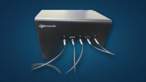
 Power measurementMulti-Channel Power MeterFive fiber-coupled channels measured at once, up to 50 W each, with logging software.View product →
Need a complete calibration or verification station for your device? See IZAK system design and development.
Frequently asked questions
QWhat is the difference between verification and validation for a medical laser?
QWhich standards apply to testing a surgical or aesthetic laser?
QHow accurate must the output of a medical laser be?
Standards and references
- ISO 13485:2016, Medical devices — Quality management systems — Requirements for regulatory purposes (clauses 7.3.6 and 7.3.7).
- IEC 60601-2-22:2019+AMD1:2026, Medical electrical equipment — Part 2-22: Particular requirements for the basic safety and essential performance of surgical, cosmetic, therapeutic and diagnostic laser equipment.
- IEC 60825-1:2014, Safety of laser products — Part 1: Equipment classification and requirements.
- ISO 14971:2019, Medical devices — Application of risk management to medical devices.
- IEC 62366-1:2015+AMD1:2020, Medical devices — Part 1: Application of usability engineering to medical devices.
- U.S. FDA, Laser Products – Conformance with IEC 60825-1 Ed. 3 and IEC 60601-2-22 Ed. 3.1 (Laser Notice No. 56), guidance, 2019, revised 2023.
- ILAC-G8:09/2019, Guidelines on decision rules and statements of conformity.
Tzachi Sabati
CEO, IZAK Scientific
Physicist specializing in photonics and quantum technologies, with deep expertise in quantum sensors and advanced optical systems. Leads the Advanced Quantum Lab course at the Technion, bridging academic excellence with industry innovation. At IZAK Scientific, provides cutting-edge photonics-based solutions, developing customized inspection and sensing systems for R&D and production. Passionate about advancing quantum sensing applications and integrating novel technologies to meet industry needs.
