

In short
- Decide the quantity first. Total output of an LED (lumens or watts) is flux. Light falling on a surface (lux or W/m²) is irradiance. They need different instruments.
- Flux needs an integrating sphere. The sphere collects light from every direction, so the result does not depend on the beam pattern. Calibrate it by substitution with a reference lamp and correct for self-absorption.
- Irradiance needs a cosine corrector. A diffuser in front of the spectrometer or detector weights light by the cosine of its arrival angle, as a real surface does.
- Do not convert one into the other without data. Turning an on-axis irradiance reading into flux needs the full angular pattern. A 10° error in the assumed half angle gives about a 28% error in flux.
Flux or irradiance: decide what you need to measure
Most LED measurement problems start with the wrong question. “How bright is this LED?” can mean four different quantities, and an integrating sphere and a cosine corrector each answer only some of them. Before you choose the optics in front of your spectrometer or photometer, write down the quantity your specification, customer or standard asks for.
| Quantity | Radiometric / photometric unit | Question it answers | Right front-end |
|---|---|---|---|
| Flux (total) | W / lm | How much light does the LED emit in all directions? | Integrating sphere (4π or 2π geometry) |
| Irradiance / illuminance | W/m² / lx | How much light reaches this surface? | Cosine corrector at the surface |
| Intensity | W/sr / cd | How much light per unit solid angle in one direction? | Detector at a known distance and aperture (averaged LED intensity) |
| Radiance / luminance | W/(m²·sr) / cd/m² | How bright does the emitting surface look? | Imaging or narrow field-of-view optics |
Datasheet binning, lamp efficacy (lm/W) and colour of the total output are flux measurements. UV-curing dose, horticultural photon flux density on the canopy, display backlight levels and workplace lighting are irradiance or illuminance measurements. For background on the units, see our article on the basics of radiometry and photometry.
How an integrating sphere measures LED flux
An integrating sphere is a hollow sphere with a diffuse, highly reflective coating. Light from the LED is reflected many times before it reaches the detector port, so the detector sees the same wall radiance whatever the direction in which the light left the LED. A narrow 15° LED and a wide 120° LED with the same flux give the same reading. That is the whole point of the sphere.
Each reflection multiplies the wall radiance. The gain over a single reflection is the sphere multiplier M = ρ / [1 − ρ(1 − f)], where ρ is the wall reflectance and f is the fraction of the sphere surface taken by ports. The irradiance on the sphere wall, which a detector at a port sees, is approximately E = Φ·M / (π D²) for flux Φ and sphere diameter D.
With ρ = 0.98 and 1% port area, M ≈ 32. The high multiplier is why sphere results depend strongly on coating condition.
Keep total port area to about 5% of the sphere surface or less, so the integration stays uniform.
A baffle between the LED and the detector port blocks first-strike light. Without it, the reading again depends on the beam pattern.
A common rule keeps the device under test to about one tenth of the sphere diameter, or larger only with self-absorption correction.
4π or 2π geometry
In 4π geometry the source sits at the centre of the sphere and all its emission, backward light included, is collected. This suits lamps and LED modules that emit in many directions. In 2π geometry the LED is mounted at a port on the sphere wall and only its forward hemisphere enters. CIE 127 describes this geometry for LEDs that emit only forward. It also keeps the heat sink, drive cabling and temperature control outside the sphere, which helps for high-power LEDs that must be measured at a controlled junction or board temperature.
Calibration by substitution and self-absorption
A sphere is a relative instrument. It is calibrated by substitution: a reference lamp of known total spectral flux is measured, then the LED under test is measured in the same position. Anything in the sphere absorbs light, including the LED package, its board and the mount. A small auxiliary lamp, shielded from the detector, is read once with the reference lamp in place and once with the device under test in place; the ratio corrects the result for the different absorption of the two. Skip it and a dark, large LED board reads low.
Spectroradiometer, not filtered photometer
For coloured, blue-pumped white and UV LEDs, use a calibrated spectroradiometer behind the sphere and compute photometric and colour quantities from the spectrum. A filtered photometer head whose response deviates from the V(λ) curve can give large spectral-mismatch errors on narrowband sources. With the spectrum in hand you also get dominant wavelength, chromaticity, and CCT and Duv: try our CCT and Duv calculator.
How a cosine corrector measures irradiance
A real surface receives light from a direction θ off its normal with an efficiency of cos θ, because the beam footprint spreads over a larger area. An irradiance sensor must do the same. A bare fiber tip or a detector behind a flat window does not: its acceptance is narrow, and at large angles reflection losses reduce it further. A cosine corrector, usually a diffusing disc of PTFE or opal glass in a shaped housing, gives an angular response close to cos θ over a wide field.
The quality of that response is expressed by the directional response error f₂, defined for illuminance meters in ISO/CIE 19476. A small f₂ matters most when light arrives from wide angles: near an extended source, under an LED array, inside a curing chamber or in a room. For a single small LED on the sensor axis, the cosine response hardly matters; for a large panel at short distance, it dominates the uncertainty.
Far field and distance
Point-source formulas assume the detector is far from the source. For a uniform disc source, the inverse-square law is within 1% at a distance of five source diameters and within 0.25% at ten. Closer than that, measure at the real working distance rather than calculate from intensity.
What irradiance cannot tell you
A cosine-corrected reading tells you the irradiance at one point. To get flux from it you must know the angular distribution of the LED. For a generalised Lambertian emitter with half-intensity angle θ½, the intensity is I(θ) = I₀ cosmθ with m = −ln 2 / ln(cos θ½), and the flux is Φ = 2π I₀ / (m + 1). Assume the wrong θ½ and the flux is wrong in proportion: a beam of 100° full width read as a Lambertian 120° beam overestimates flux by about 28%. For an accurate angular pattern you need a goniophotometer or a sphere.
Integrating sphere and LED irradiance calculator
Mode 1 sizes an integrating sphere: port fraction, sphere multiplier, wall irradiance at the detector and a check of the device size. Mode 2 turns LED flux and beam angle into intensity and irradiance on a plane, on axis and off axis.
Sphere mode uses the ideal sphere equation with a uniform wall and ports counted as zero reflectance; real spheres also lose light on baffles, the device and its mount. Irradiance mode treats the LED as a point source with a cosmθ pattern; check the far-field ratio before trusting it close to large arrays.
Worked example: one blue LED, two measurements
A 450 nm LED emits a radiant flux of 1.0 W with a near-Lambertian pattern (θ½ = 60°, 120° full beam).
Total flux in a 250 mm sphere, 2π geometry. The LED port is 50 mm and the fiber port to the spectroradiometer is 12.7 mm. Port fraction f = (50² + 12.7²) / (4 × 250²) = 1.06%. With a wall reflectance of 0.98 the sphere multiplier is M = 0.98 / [1 − 0.98 × 0.9894] = 32.2, and the wall irradiance at the detector port is 1.0 × 32.2 / (π × 0.25²) ≈ 164 W/m², or 16.4 mW/cm². That is plenty of signal; most set-ups add attenuation before the spectrometer. Now let the coating age to ρ = 0.97: M drops to 24.1 and the signal by about 25%. One percentage point of reflectance changes the signal by a quarter, which is why the sphere is recalibrated with a reference lamp and checked regularly, not trusted from its last certificate.
Irradiance on a target 300 mm away. On-axis intensity I₀ = Φ / π = 0.318 W/sr, so the irradiance is I₀ / d² = 0.318 / 0.3² ≈ 3.54 W/m². At 100 mm off axis on the same plane the angle is 18.4°, and the irradiance falls as cosm+3θ to 2.86 W/m², 81% of the centre value. The emitter is 3 mm across, so the distance is 100 source sizes: the point-source model holds.
The trap. Suppose the same 3.54 W/m² had been read from an LED with a 100° beam (θ½ = 50°, m = 1.57) and converted to flux by assuming a Lambertian pattern. With I₀ = 0.318 W/sr the calculation would report Φ = π I₀ = 1.00 W, while the true flux is 2π I₀/(m + 1) = 0.78 W: 28% high from a single wrong assumption. If you need flux, measure flux.
| Need | Integrating sphere | Cosine corrector |
|---|---|---|
| Total flux, efficacy, LED binning | Yes: insensitive to beam pattern | Only with a measured angular pattern |
| Dose or irradiance on a surface | No | Yes, at the working distance |
| Colour of the total output | Yes: spatially averaged spectrum | Colour in one direction only |
| Uniformity across a target | No | Yes: scan or use several heads |
| Main error sources | Coating ageing, self-absorption, first-strike light, temperature | Directional response (f₂), alignment, distance, near-field geometry |
| Throughput in production | High, with a fixed 2π port fixture | High for fixed geometry, sensitive to positioning |
Common mistakes in LED flux and irradiance measurements
- Measuring before the LED is stable. LED output and wavelength change with junction temperature. Fix the drive current, the board temperature and the settling time, and record them with the result.
- No baffle, or the wrong one. Light that strikes the detector port area directly makes the sphere reading depend on the LED’s beam pattern again.
- No self-absorption correction. A large or dark device board in the sphere absorbs light that the reference lamp did not have to share.
- A bare fiber used as an irradiance sensor. Without a cosine corrector the reading depends on the angle of arrival and is not irradiance.
- Inverse-square used too close. Under about five source sizes the point-source model fails. Measure at the working distance.
- Photometer on a narrowband LED. Spectral mismatch can dominate the uncertainty. Measure the spectrum and calculate.
Integrating sphere stations in production test
In a production line the same physics applies, with two extra demands: speed and a record for every unit. An integrating sphere with a fixed 2π port fixture gives repeatable seating and keeps the device at a controlled temperature. Additional channels on the same sphere can measure several things at once. In an IZAK bare-LED inspection system, one sphere feeds a calibrated power channel, a spectrometer channel and a fast photodiode channel for the temporal pulse shape, with software that applies pass/fail criteria and writes a report. We describe that system in LED inspection, part 1: the integrating sphere. For broader context on test strategies, see radiometry and LED quality assurance.
IZAK products for this application
IZAK designs radiometric and LED test systems to the measurement you need: integrating-sphere stations for flux and spectrum, irradiance and narrow-field radiometers, and vision-based LED inspection for assembled boards.
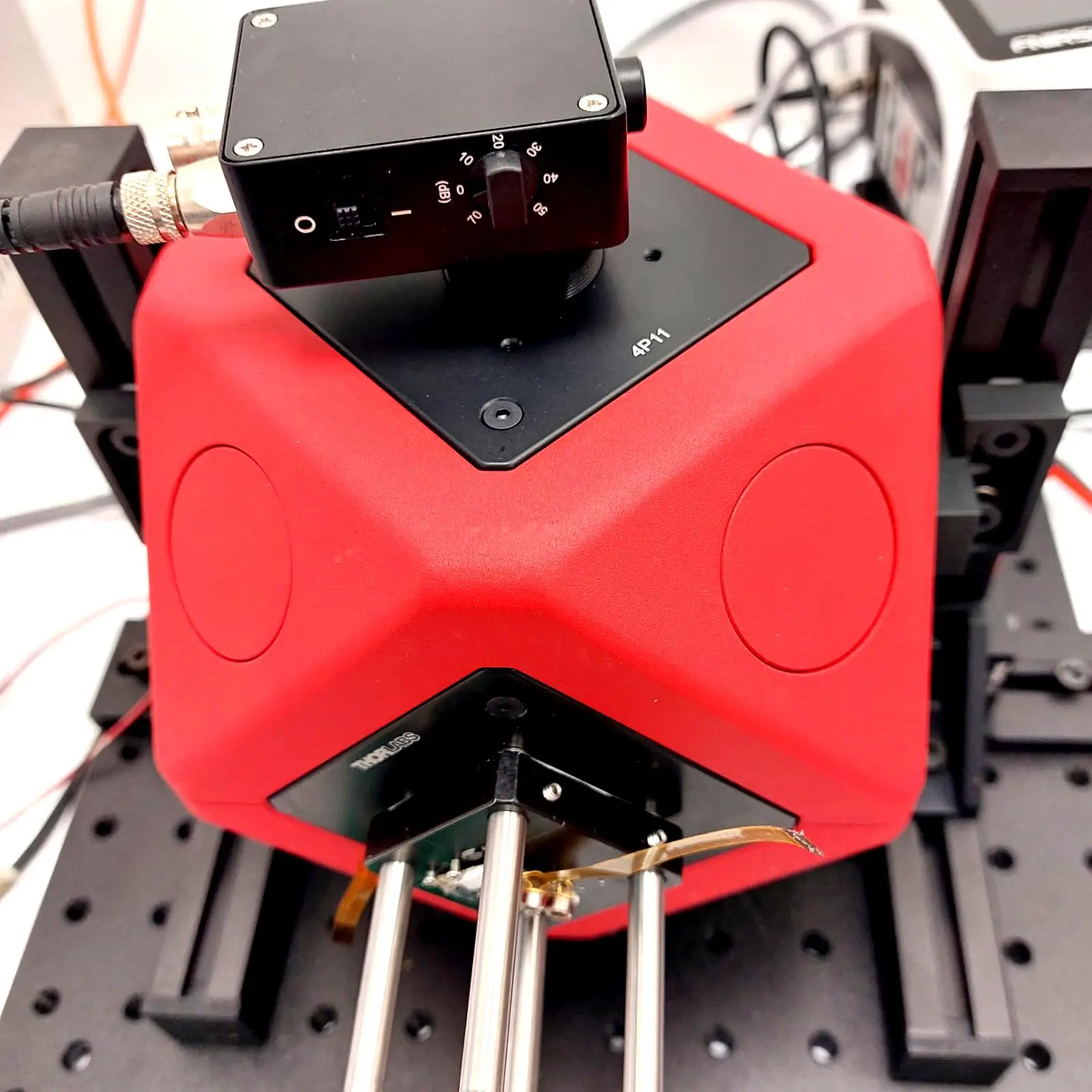 Custom test systemsIntegrating Sphere LED Test StationsPower, spectrum and pulse-shape channels on one sphere, with pass/fail criteria and reports.View service →
 RadiometryMulti-Channel Spectro-RadiometerVIS or cooled IR spectrometer with radiometer channels, narrow field of view and flat response to 5 MHz.View product →
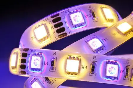 ProductionLED TesterChecks colour, position and on/off state of every LED on a board, with pass/fail and a CSV log.View product →
Not sure which front-end your measurement needs? Book a radiometry consultation.
Frequently asked questions
QWhen should I use an integrating sphere instead of a cosine corrector?
QHow large should an integrating sphere be for LED measurements?
QCan I calculate LED flux from an irradiance measurement?
Standards mentioned
- CIE 127:2007, Measurement of LEDs.
- CIE S 025/E:2015, Test Method for LED Lamps, LED Luminaires and LED Modules.
- ISO/CIE 19476:2014, Characterization of the performance of illuminance meters and luminance meters.
- CIE 84-1989, The measurement of luminous flux.
Tzachi Sabati
CEO, IZAK Scientific
Physicist specializing in photonics and quantum technologies, with deep expertise in quantum sensors and advanced optical systems. Leads the Advanced Quantum Lab course at the Technion, bridging academic excellence with industry innovation. At IZAK Scientific, provides cutting-edge photonics-based solutions, developing customized inspection and sensing systems for R&D and production. Passionate about advancing quantum sensing applications and integrating novel technologies to meet industry needs.
Get new IZAK guides and tools by email
One short email a month: new technical articles, free calculators and product updates in laser measurement and electro-optics. No spam, unsubscribe anytime.
