

In short
- Transmittance is a ratio. T(λ) is the light that leaves the sample divided by the light that entered it, measured against a 100% baseline and a dark reading taken with the same set-up.
- The set-up is part of the result. Spectral bandwidth, angle of incidence, beam convergence and polarization change the number. A result without them cannot be compared or put into a specification.
- High optical density needs a different method. Above about OD 3–4 stray light inside the instrument sets the reading, not the filter. The stack calculator shows where your measurement saturates.
- Know which transmittance you report. Material data is internal transmittance at a reference thickness; a part is specified by external transmittance, surfaces included. The second calculator converts one to the other.
What spectral transmittance means
Spectral transmittance is the fraction of the incident light that passes through a sample at each wavelength: T(λ) = Φt(λ) / Φi(λ). It is the most common measurement in the optical analysis of windows, filters, lenses, coatings, protective covers and optical materials, and it is the number most optical specifications quote.
Three variants are worth separating before any measurement starts:
- Regular (direct) transmittance – only the light that keeps its direction. This is what a standard spectrophotometer measures, and what matters for imaging and laser optics.
- Total transmittance – direct plus scattered light, collected with an integrating sphere. The difference between total and regular transmittance is the diffuse part, and its share of the total is the haze.
- Internal and external transmittance – internal transmittance describes the bulk material only; external transmittance includes the reflection at both surfaces and is what the user of the part receives.
Transmittance is often given on a logarithmic scale as optical density, OD = −log₁₀(T). OD 1 is 10%, OD 2 is 1%, OD 3 is 0.1%. Because OD values add when filters are stacked, laser safety and attenuation work is usually done in OD.
How a transmittance measurement works
Every transmittance measurement compares three readings taken with the same source, optics and detector settings:
- Dark reading Dthe beam blocked, to record detector offset and room light
- Reference reading Rthe 100% baseline: empty beam, or a reference sample if you need a relative result
- Sample reading Sthe sample in the beam, in the same position and orientation every time
- TransmittanceT = (S − D) / (R − D), calculated at every wavelength
A single-beam instrument records R and S one after the other, so any drift of the source or detector between the two readings goes straight into the result. A double-beam instrument splits the light and measures sample and reference at almost the same time, which cancels most of the drift. In both cases the baseline should be measured again whenever the set-up, the bandwidth or the temperature changes, and checked with a known reference such as a calibrated neutral-density filter.
At a single laser wavelength the same ratio is measured with a laser and a power meter: power with the sample, power without it, and a dark reading. A second detector on a pick-off beam, used as a monitor, removes the laser’s power fluctuations from the ratio.
Six set-up choices that change the result
A bandwidth wider than the feature smears it: narrow lines look shallower and filter edges look softer. Keep the bandwidth at about one tenth of the narrowest feature you measure.
Interference filters and coatings shift to shorter wavelengths when tilted. Measure at 0° for a material, and at the angle of use for a filter in a system.
A converging beam is a spread of angles, so a narrow filter looks wider and its peak looks lower than in a collimated beam. State the f-number or cone angle.
A thick or wedged sample shifts and refocuses the beam on the detector. If the detector is not uniform, that shift reads as a loss. An integrating-sphere detector reduces the effect.
At oblique incidence, s and p light are transmitted differently. Measure both, or measure with a known polarization state, and report it.
Fingerprints, dust and condensation lower T; temperature shifts absorption edges and filter passbands. Clean, stabilize and handle samples by the edges.
Filters at an angle. The center wavelength of an interference filter moves to shorter wavelengths as it is tilted: λ(θ) = λ₀ · √(1 − (sin θ / neff)²), where neff is the effective index of the coating (often between about 1.5 and 2.2; filter data sheets sometimes give it). A 1064 nm filter with neff = 2.0 moves about 4 nm at 10°. For a 3 nm wide laser-line filter that shift is larger than the passband half-width, so a tilted measurement and a straight one give very different answers.
Filter shift with angle of incidence
Enter the center wavelength at normal incidence, the effective index of the filter and the angle. The tool returns the new center wavelength and the shift, for a collimated beam.
The shift grows with the square of the angle at small angles, so 5° gives about a quarter of the 10° shift. In a converging beam each ray has its own angle and the passband widens and moves by roughly half the shift at the edge ray.
Measuring high optical density: stacks, blocking filters and attenuators
Laser safety windows, blocking filters and attenuator stacks are specified at OD 4, 6 or more. A standard spectrophotometer cannot verify those values directly. A small amount of light always reaches the detector by the wrong path – scattered inside the monochromator, or at wavelengths outside the band being measured – and that stray light adds to the tiny signal through the sample. When the sample transmits less than the stray light, the reading stops falling and the measured OD saturates. With 0.01% stray light, the reading cannot go much beyond OD 4, whatever the filter really does.
Practical ways to measure high OD:
- Measure the pieces, then add. Measure each filter of a stack within the instrument’s range and add the OD values. Tilt reflective filters slightly, because reflections between them can send light back through the stack.
- Attenuate the reference. Put a calibrated attenuator in the reference beam so that sample and reference signals are of similar size. The detector then works in its most linear range.
- Use a laser and a power meter. At a single wavelength, a laser with a band-pass filter and a sensitive detector can cover OD 6–8, provided the detector is linear across the range and the set-up is shielded from room light.
- Check linearity. Measure a known stack of calibrated filters and compare the sum with the reading before you trust a high-OD result.
The same arithmetic is used when you plan attenuation for a camera or a power sensor. Our article on attenuation for laser beam profilers shows how to bring a laser beam down to a level a sensor can measure.
Filter stack: transmittance, OD and stray-light limit
Enter up to four filters, each as OD or as transmittance in %. The tool adds them and shows what an instrument with the given stray-light level would actually read. Leave unused rows empty.
Model: reading = (T + s) / (1 + s), where s is the stray light as a fraction of the reference signal. Reflections between filters are ignored. Stray light depends on the wavelength and on the instrument; use the value from its specification or from a blocking-filter test.
Internal transmittance, thickness and surface loss
Optical material data usually lists internal transmittance at a reference thickness, often 10 mm or 25 mm. It excludes the surfaces, so it is close to 100% for good glass in its transparent range. Your part has a different thickness and two surfaces, and both change what you measure.
Internal transmittance scales with thickness as a power: Ti(d₂) = Ti(d₁)d₂/d₁. The surfaces are then added with the Fresnel reflection R = ((n − 1)/(n + 1))² at each face, including the light that bounces between the two faces: T = (1 − R)² Ti / (1 − R² Ti²). For an uncoated glass window near n = 1.52, the surfaces alone cost about 8%, which is usually much more than the bulk absorption.
From material data to your part
Enter the refractive index, the internal transmittance from the material data and its reference thickness, and the thickness of your part. The tool returns the internal and external transmittance of an uncoated part at normal incidence.
Assumes polished, parallel, uncoated faces, no scattering and incoherent reflections. Going the other way – from a measured part back to the material – is the job of the reflection-and-absorption calculator in our optical analysis guide.
Scattering samples: total transmittance and haze
Diffusers, frosted or molded plastics, ceramics, biological tissue and coated covers scatter part of the light. A standard instrument with a small detector misses the scattered part and reports it as a loss. To measure what really passes, put the sample at the entrance port of an integrating sphere: the sphere collects light at all forward angles and gives the total transmittance. Remove the direct beam through an exit port and the sphere measures only the diffuse part; haze is the diffuse share of the total. The same sphere technique is used for LED flux, as described in our integrating sphere article.
Measuring at a laser wavelength
Many specifications ask only for T at one laser line – 532, 1064 or 1550 nm, for example. A laser and a power meter give that number directly, with less effort than a full spectrum, but they bring their own pitfalls:
- Interference fringes. A narrow-linewidth laser is coherent across a thin, parallel window, so the two surfaces form an etalon. T then changes with thickness, angle and temperature by several percent. Tilt the sample slightly, use a wedged sample, or average over angle.
- Power stability. Use a monitor detector, or alternate sample and reference readings quickly.
- Detector uniformity and beam size. Keep the beam well inside the detector and away from its edges, or use an integrating-sphere detector.
- Damage and heating. Check the fluence against the damage threshold of the sample, especially for pulsed lasers and absorbing filters.
Error budget at a glance
| Error source | What it does to T | How to control it |
|---|---|---|
| Baseline drift | Offsets the whole curve | Double beam, frequent baseline, warm-up |
| Stray light | Caps high OD; lifts deep minima | Band-pass before the detector, reference attenuation, measure stack pieces |
| Detector non-linearity | Wrong ratio when S and R differ strongly | Calibrated neutral-density checks, attenuated reference |
| Spectral bandwidth | Shallower lines, softer edges | Bandwidth ≤ about 1/10 of feature width |
| Angle and convergence | Filter edges shift and widen | Collimate, align, state the angle and cone |
| Polarization | s and p differ at oblique incidence | Polarizer or depolarizer, report the state |
| Beam displacement | False loss on a non-uniform detector | Integrating-sphere detector, small beam |
| Interference (laser) | Periodic ripple of several % | Tilt, wedge, angle averaging |
| Sample condition and temperature | Lower T, shifted edges | Cleaning, handling, temperature control |
What a transmittance result should state
A transmittance value can only be compared with a specification if the conditions come with it. ISO 15368 describes the measurement of transmittance of plane-parallel elements and reflectance of plane surfaces; whichever procedure you follow, report at least:
- Wavelength range, step and spectral bandwidth
- Angle of incidence, beam convergence and polarization
- Regular or total transmittance; internal or external
- Sample thickness, coating and orientation (which side faces the source)
- Reference used for the 100% baseline and how it is calibrated
- Temperature, and the estimated uncertainty
From a lab spectrum to a production test
In production the question is usually narrower: does every window, filter or cover pass its transmittance limit at a few wavelengths, in a few seconds? That calls for a dedicated station rather than a general-purpose spectrophotometer: stable sources at the test wavelengths, a fixture that places each part the same way, automatic dark and reference readings, and software that applies the limits and stores a record per unit. IZAK designs such electro-optical test stations, from the optical design to the software.
IZAK products for this application
Instruments for spectral and laser measurements, and custom stations when transmittance has to be tested on every unit.
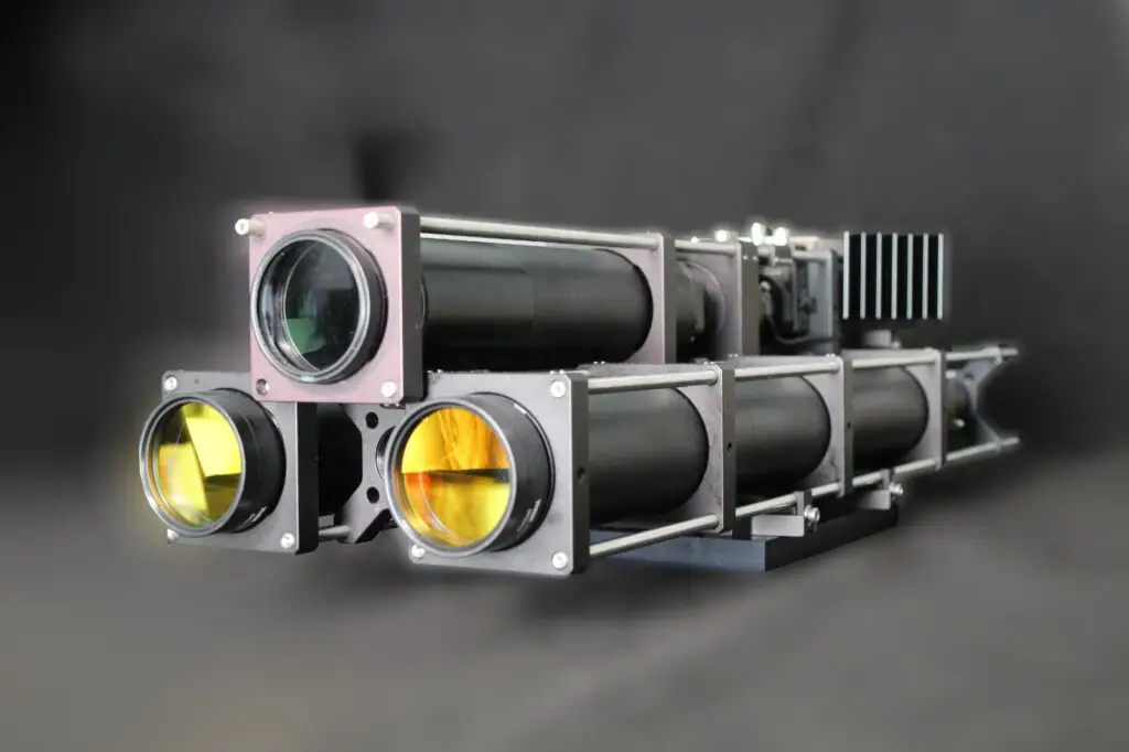 RadiometryMulti-Channel Spectro-RadiometerFast spectral and radiometric measurement with selectable spectral channels and a narrow, uniform field of view.View product →
 Laser beam analysis · UV to LWIRLaser Beam ProfilersISO 11146 beam width, M², divergence and pointing, with attenuation planned for your laser power.View product →
Need a transmittance test that no catalog instrument covers? We design and build electro-optical test systems →
What to send us for a transmittance test set-up
With these details an engineer can propose a method or a test station in one reply:
- The partwindow, filter, cover or material; size, thickness, coating
- Wavelengthsa full spectrum, a band or a few laser lines
- The limitT or OD to verify, and its tolerance
- Geometryangle of incidence, beam convergence, polarization in use
- Throughputsamples in the lab or every unit on a line, and the cycle time
- Recordsreport format, traceability and data interfaces
Frequently asked questions
QHow is spectral transmittance measured?
QHow do I convert transmittance to optical density?
QWhy can my spectrophotometer not measure an OD 6 filter?
QWhat is the difference between internal and external transmittance?
QWhy does a filter’s transmittance change with angle?
Tzachi Sabati
CEO, IZAK Scientific
Physicist specializing in photonics and quantum technologies, with deep expertise in quantum sensors and advanced optical systems. Leads the Advanced Quantum Lab course at the Technion, bridging academic excellence with industry innovation. At IZAK Scientific, provides cutting-edge photonics-based solutions, developing customized inspection and sensing systems for R&D and production. Passionate about advancing quantum sensing applications and integrating novel technologies to meet industry needs.
Get new IZAK guides and tools by email
One short email a month: new technical articles, free calculators and product updates in laser measurement and electro-optics. No spam, unsubscribe anytime.
