

In short
- A Pockels cell driver is a fast high-voltage switch with a capacitive load. It must swing kilovolts in nanoseconds, at the right moment, without ringing.
- Voltage scales with wavelength. The half-wave voltage grows roughly in proportion to λ, and a double-pass Q-switch needs only the quarter-wave voltage.
- Every picofarad costs current and power. Edge current is C·V/tᵣ, average power is C·V²·f, and a metre of coax can add ten times the capacitance of a small cell.
- Jitter and accuracy set the optical result. The edge plus jitter must fit between laser pulses, and a 2% voltage error already leaks 0.1% of the light.
What a Pockels cell driver has to do
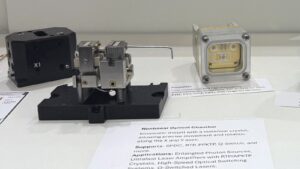
A Pockels cell is an electro-optic crystal between two electrodes. At its half-wave voltage it rotates linear polarization by 90°, so with a polarizer it becomes a shutter that switches in nanoseconds. Q-switched lasers, regenerative amplifiers and pulse pickers all depend on it.
The crystal is the easy part. The hard part is the Pockels cell driver, the high-voltage switcher that moves the electrodes between voltage states. Electrically the cell is a small capacitor, typically a few to a few tens of picofarads. It only works optically if that capacitor is charged to the right voltage, fast, at a precise time, without ringing. Below, each requirement is worked through with numbers.
For the electro-optic effect itself, see our overview of high-voltage switches in optics and quantum technologies.
Drive voltage: half-wave, quarter-wave and wavelength
Between crossed polarizers a cell driven to voltage V transmits
T = sin²(π·V / 2Vπ)
where Vπ is the half-wave voltage. Three practical rules follow:
- Vπ scales with wavelength. For both longitudinal and transverse cells the retardation is proportional to V/λ, so Vπ grows roughly in proportion to λ. A cell rated at 6.6 kV half-wave at 1064 nm needs about 3.3 kV at 532 nm and about 9.6 kV at 1550 nm. Dispersion of the refractive index and of the electro-optic coefficient changes this by a few percent, so confirm with the cell data at your wavelength.
- Geometry matters. In a longitudinal cell (field along the beam) Vπ does not depend on the aperture. In a transverse cell (field across the beam) Vπ scales with the ratio of thickness to length, so a long, thin crystal or two crystals in series lower the voltage, at the cost of aperture.
- Double pass halves the voltage. In a Q-switch or regenerative amplifier the beam passes the cell twice, so the quarter-wave voltage Vπ/2 already gives a 90° rotation on the round trip. A single-pass pulse picker or shutter needs the full Vπ.
A design rule on top: the cell sees the difference between its electrodes, so switching both sides in opposite directions halves the voltage each switch must hold.
Rise time and the capacitive load
To change the voltage across a capacitance C by V in a time tᵣ, the driver must deliver a current of roughly I = C·V / tᵣ. With 3.3 kV, 5 ns and 43 pF that is about 28 A, for a few nanoseconds, from a supply that may average only a few milliamps. That is why fast drivers use stacks of switching transistors with energy storage right at the output, and why layout matters as much as the schematic.
The capacitance is rarely just the cell: add the mount, the connector and above all the lead. Coaxial cable has roughly 50–100 pF per metre, so keep the high-voltage lead as short as the mechanics allow.
There is a second effect. Signals in coax travel at about two thirds of the speed of light, roughly 5 ns per metre. When the one-way delay of the lead is more than about one sixth of the rise time, the lead stops behaving like a lumped capacitor and becomes a transmission line. During the edge the driver then sees the cable impedance, so with 50 Ω and 3.3 kV it must supply about 66 A, and reflections from the unmatched cell can ring at the crystal. For a 5 ns edge the lumped limit is a lead of about 16 cm. Beyond that, either the driver is mounted at the cell or the output network is designed for the line, and in both cases the edge must be checked at the cell, not at the driver output.
Measure the optical edge, not only the electrical one. A high-voltage probe tells you what the electrodes do; a fast photodiode behind the analyzer tells you what the light does. They differ, because transmission follows sin². For a linear voltage ramp that ends exactly at Vπ, the 10–90% optical rise is about 0.74 of the electrical 10–90% time, and for an exponential (RC) edge about 0.62. If the drive overshoots or stops short of Vπ, the optical edge distorts further. Timing the laser pulse itself is covered in our guide to pulsed laser beam profiling.
Jitter and the timing budget
Rise time decides how fast the gate moves; jitter decides when. Jitter is the random shot-to-shot variation of the output edge relative to the trigger. It adds to every timing budget in the system:
- Q-switching. The laser pulse appears a build-up time after the cell opens. Driver jitter adds directly to the output pulse timing jitter, which matters when the laser must be synchronised to a detector, a second laser or a range gate.
- Pulse picking. To select one pulse from an oscillator train, the gate must open completely after the previous pulse and before the chosen one. As a working rule, the full transition (about 1.25 times the 10–90% rise time for a near-linear edge) plus a ±3σ jitter window must fit inside the pulse spacing.
- Regenerative amplifiers. The cell switches in and out within one cavity round trip, so both edges and their jitter count.
Example: an 80 MHz oscillator has pulses every 12.5 ns. A 5 ns rise time and 100 ps rms jitter need 1.25 × 5 + 6 × 0.1 = 6.85 ns, which fits with about 5.6 ns to spare. At 200 MHz the spacing is 5 ns and the same driver cannot pick a clean single pulse: the neighbours leak. Either the edge must be much faster or picking must happen at a lower rate.
Jitter comes from the trigger input, the gate drivers of the switch stack and ripple on the high-voltage supply. Measure jitter as a histogram of the optical edge against the trigger, over thousands of shots. Synchronising triggers, delays and acquisition is typical work for an FPGA, as discussed in the best use of FPGA in electro-optics set-ups.
Repetition rate, average power and piezoelectric ringing
Each on/off cycle charges the load to V and discharges it again. The energy C·V² per cycle ends up as heat in the driver’s switches and resistors, so the average power is P = C·V²·f and the average supply current is C·V·f. Both grow linearly with repetition rate and with total capacitance, and the power grows with the square of the voltage. This sets the supply size, the heat sinking and the burst limits of a driver.
The crystal adds its own limit. Most electro-optic crystals are also piezoelectric: a fast voltage step launches acoustic waves that modulate the birefringence for microseconds afterwards. At some repetition rates these resonances build up and the extinction collapses. Crystal choice therefore depends on the repetition rate: some materials ring at tens of kilohertz, while others, such as RTP, are chosen for high-repetition-rate work because they show little ringing into the megahertz range. Check the cell at your actual rate, not only its static extinction.
Voltage accuracy, ringing and contrast
Because transmission follows sin², a voltage error ε (as a fraction of the ideal drive) leaves a fraction sin²(π·ε/2) of the light in the wrong polarization. This applies both to a residual voltage in the closed state and to a shortfall or overshoot in the open state:
| Voltage error or ringing | Light in the wrong state | Contrast limit |
|---|---|---|
| 1% | 0.025% | about 4,000:1 |
| 2% | 0.10% | about 1,000:1 |
| 5% | 0.62% | about 160:1 |
| 10% | 2.4% | about 40:1 |
Good cells reach static contrast ratios of about 1,000:1 or better. A driver that rings by 5% wastes most of that: in a Q-switch it means pre-lasing and lost hold-off, in a pulse picker pre- and post-pulses. Flat-top accuracy and clean settling matter as much as rise time.
Worked example: a Q-switched laser at 1064 nm
A diode-pumped Q-switched laser uses a double-pass cell with Vπ = 6.6 kV at 1064 nm. The cell has 8 pF, the mount and connector add 5 pF, and the driver sits 30 cm away on coax with 100 pF/m. Target: 5 ns rise time at 10 kHz, ±2% flat-top accuracy, 100 ps rms jitter.
| Quantity | Calculation | Result |
|---|---|---|
| Drive voltage (quarter-wave) | 6.6 kV / 2 | 3.3 kV |
| Total capacitance | 8 + 0.3 × 100 + 5 | 43 pF |
| Edge current (lumped) | 43 pF × 3.3 kV / 5 ns | 28 A |
| Energy per cycle | 43 pF × (3.3 kV)² | 0.47 mJ |
| Average power at 10 kHz | 0.47 mJ × 10 kHz | 4.7 W |
| Average supply current | 43 pF × 3.3 kV × 10 kHz | 1.4 mA |
| Cable delay | 0.3 m at 0.66 c | 1.5 ns (above the 0.83 ns lumped limit) |
| Leakage from ±2% error | sin²(π × 0.02 / 2) | 0.10% |
Two lessons stand out. First, the cable carries 30 of the 43 pF: moving the driver onto the cell would cut the average power by about 70%. Second, even 30 cm is electrically long for a 5 ns edge, so the rise time must be verified at the cell. Now stretch the cable to 3 m: the load becomes 313 pF, the average power 34 W and the average current 10 mA, for exactly the same optical job. Try your own numbers below.
Pockels cell drive and timing budget
Choose Q-switch for a double-pass cell at the quarter-wave voltage (also regenerative amplifiers), or Picker for a single-pass cell at the half-wave voltage (pulse pickers, shutters). Then enter your cell, lead and timing. The tool scales the half-wave voltage to your wavelength, adds up the load, and returns edge current, average power and current, cable delay, the pulse-picking timing budget and the leakage caused by a voltage error or ringing.
Assumptions: Vπ proportional to wavelength (dispersion neglected); lumped edge current C·V/tᵣ; full charge and discharge every cycle (P = C·V²·f); cable velocity 0.66 c; lumped if one-way delay ≤ tᵣ/6; pulse-picking budget 1.25·tᵣ + 6σ ≤ pulse spacing; leakage sin²(π·ε/2). Piezoelectric ringing of the crystal is not modelled. Use the results for sizing and comparison, then verify at the cell with an optical measurement.
Driver topologies compared
| Topology | How it works | Strengths | Limits |
|---|---|---|---|
| Single switch stack | A series stack of fast transistors switches the cell; a resistor recharges it | Simple, fast one edge | Slow, power-hungry second edge; limited repetition rate |
| Push-pull stacks | One stack charges, a second discharges; both edges are active | Fast rise and fall, variable gate width, high repetition rates and bursts | More parts, timing of two stacks must be matched |
| Differential (two-sided) drive | Each electrode is switched by its own stack in opposite directions | Each switch holds half the voltage; full Vπ with lower-voltage parts | Two outputs to route and balance |
| Avalanche or Marx-type pulsers | Stored energy is released through a chain of avalanching stages | Sub-nanosecond edges | Fixed pulse shape and width, low average repetition rate |
For most Q-switching and pulse-picking work, push-pull transistor stacks are the practical choice: they control both edges, run at tens to hundreds of kilohertz and keep jitter below a nanosecond.
Specifying a high-voltage switcher: a checklist
- Voltage: Vπ or Vπ/2 at your wavelength, plus margin, and whether a single-ended or differential output suits the cell.
- Load: cell, mount and lead capacitance, and the lead length you can achieve.
- Edges: 10–90% rise and fall time measured on that load, and settling (ringing) after the edge.
- Timing: jitter (rms or peak-to-peak, stated clearly), trigger-to-output delay and its drift, minimum and maximum gate width.
- Rate: continuous repetition rate and burst rate at your voltage and load, which sets the average power.
- Interfaces: isolated trigger, voltage and current monitoring, software control of amplitude and timing.
- Safety: interlocks, shielded connectors and cables rated for the voltage, and grounding that keeps the switching noise away from detectors.
Then turn the list into an acceptance test: optical edge, jitter histogram and leakage at the real rate, with the real cable.
IZAK products for this application
IZAK designs and builds high-voltage drive electronics for electro-optic crystals, and the control and test systems around them.

Need the driver integrated with timing, interlocks and test software? See control engineering and custom electro-optical systems.
Frequently asked questions
QWhat rise time does a Pockels cell driver need?
QHow do I calculate the current and power of a Pockels cell driver?
QWhy does my Pockels cell leak light even at the right voltage?
Standards and publications
- A. Yariv and P. Yeh, Optical Waves in Crystals: Propagation and Control of Laser Radiation, Wiley, 1984 (electro-optic modulation and half-wave voltage).
- W. Koechner, Solid-State Laser Engineering, 6th ed., Springer, 2006 (Q-switching with electro-optic cells).
- B. E. A. Saleh and M. C. Teich, Fundamentals of Photonics, 3rd ed., Wiley, 2019 (Pockels effect and transmission of electro-optic shutters).
Tzachi Sabati
CEO, IZAK Scientific
Physicist specializing in photonics and quantum technologies, with deep expertise in quantum sensors and advanced optical systems. Leads the Advanced Quantum Lab course at the Technion, bridging academic excellence with industry innovation. At IZAK Scientific, provides cutting-edge photonics-based solutions, developing customized inspection and sensing systems for R&D and production. Passionate about advancing quantum sensing applications and integrating novel technologies to meet industry needs.
Get new IZAK guides and tools by email
One short email a month: new technical articles, free calculators and product updates in laser measurement and electro-optics. No spam, unsubscribe anytime.
