

In short
- Five common definitions, one beam. D4σ (second moment), 1/e² clip, FWHM, knife-edge 10/90 and 86.5% power content give the same diameter only for a clean Gaussian beam.
- D4σ is the reference. It is the ISO 11146 width, it is defined for any beam shape and it is the width used for M². It is also the most sensitive to background.
- Background is the main error. A residual offset of 0.1% of the peak can make D4σ more than twice too large. Subtract a dark frame and use the ISO 11146 integration area of three beam widths.
- Always write the definition next to the number. “2.1 mm” is not a specification; “2.1 mm D4σ at the waist, background subtracted” is.
Why one beam has several widths
A laser beam has no hard edge. Its intensity falls off gradually from the centre, so its “width” depends on where you decide the beam ends. Each common definition makes that decision differently: at a fixed fraction of the peak, at a fixed fraction of the power, or from the spread of the whole distribution.
For an ideal Gaussian (TEM₀₀) beam the definitions are linked by fixed factors, so a 1/e² diameter can be converted to FWHM or D4σ exactly. Real beams are rarely ideal. Multimode, diode, top-hat, ring-shaped and clipped beams give numbers that differ by tens of percent depending on the definition, and a camera image with an uncorrected background can change one of them by a factor of two or more. This article compares the definitions, shows where they disagree and gives you a tool to see it for yourself. For the bigger picture, start with The Complete Guide to Laser Beam Profiling.
The five definitions
| Definition | How it is calculated | Gaussian beam | Typical use |
|---|---|---|---|
| D4σ (second moment) | Four times the standard deviation of the intensity distribution along each axis, after background correction, inside an integration area | 2w | ISO 11146 width; M² and divergence; comparing beams of any shape |
| 1/e² clip | Distance between the outermost points where the intensity profile falls to 13.5% of its peak | 2w | Gaussian optics, fiber coupling, laser datasheets |
| FWHM | Distance between the points at 50% of the peak | 1.177w | Top-hat beams, imaging, quick alignment; robust to noise |
| Knife-edge 10/90 | Distance over which a moving edge transmits 10% to 90% of the power, multiplied by 1.561 to match the 1/e² diameter of a Gaussian | 2w (1.282w before scaling) | Scanning-edge and slit measurements, very small or very powerful beams |
| 86.5% power content | Diameter of the circle, centred on the centroid, that contains 86.5% of the total power | 2w | Power density, material processing, laser safety |
w is the 1/e² radius of the Gaussian beam. Clip-level widths are taken on a profile through the centre of the beam; D4σ and power content use the whole image.
Converting between definitions: Gaussian beams only
For a TEM₀₀ beam, all the definitions follow from one number. Taking the 1/e² diameter D = 2w:
- D4σ = D. For a Gaussian, the standard deviation of the intensity along one axis is σ = w/2, so 4σ = 2w.
- FWHM = 0.589 × D, or D = 1.699 × FWHM.
- Knife-edge 10/90 distance = 0.641 × D; multiplied by 1.561 it returns D. Some instruments use the 16/84 distance multiplied by 2, which gives the same result for a Gaussian.
- 86.5% power content = D, because a Gaussian beam carries 1 − e⁻² = 86.5% of its power inside the 1/e² radius.
- 1/e diameter (36.8% of the peak) = 0.707 × D, used in some older texts.
These factors are exact only for a clean Gaussian. Applied to any other shape they produce a number that looks precise but is not. To convert widths and check pixel coverage for a Gaussian beam, use the converter in the beam profiling guide; to follow a Gaussian beam through focus, use the Gaussian beam calculator.
Where the definitions disagree
The table below compares the definitions for three beam shapes generated with the same parameter w, the 1/e² radius of the Gaussian. The numbers, in units of w, were computed on a simulated sensor with no background.
| Beam shape | D4σ | 1/e² clip | FWHM | Knife-edge 10/90 | 86.5% power |
|---|---|---|---|---|---|
| Gaussian (TEM₀₀) | 2.00 | 2.00 | 1.18 | 2.00 | 2.00 |
| Top-hat (super-Gaussian, order 10) | 1.83 | 2.00 | 1.80 | 1.95 | 1.71 |
| Ring (donut, LG₀₁ mode) | 2.83 | 3.00 | 2.31 | 2.88 | 2.64 |
- Top-hat: the edges are steep, so the clip widths at 13.5% and 50% are almost equal. D4σ and power content are smaller, because most of the power sits well inside the edge. Converting the FWHM of this beam with the Gaussian factor (×1.699) would overstate its size by more than 50%.
- Ring: the peak lies on the ring, not at the centre, so the clip widths measure the outer crossing of the ring. D4σ follows the power distribution and is defined the same way as for every other shape.
- Multimode and diode beams: side lobes, hot spots and asymmetric wings make clip widths jump when a lobe crosses the clip level. D4σ changes smoothly, which is why ISO 11146 uses it for beam propagation and M².
For a non-Gaussian beam, report the width in the definition the application needs, and never convert one definition into another with Gaussian factors.
Beam width explorer
Choose a beam shape, a residual background and an integration area. The explorer simulates the image on the sensor, calculates all five widths and compares them with the same beam without background. Enter the 1/e² diameter of your beam to see the results in millimetres.
D4σ1/e²FWHMprofile through the centre
Model: noise-free simulated image, 40 samples per beam diameter, background modelled as a uniform offset. Real images also carry noise, which makes the background effect larger.
Background, noise and the ISO 11146 aperture
The second moment weights every pixel by its squared distance from the centroid. Pixels far from the beam contribute little signal, but they are many and their weight is large. A small uniform offset, left over from the camera’s dark level, ambient light or a poorly subtracted reference, therefore adds a large term to the variance. In the explorer, a residual background of 0.1% of the peak, with the beam covering one sixth of the window, makes D4σ more than twice too large, while the 1/e² and FWHM widths change by less than 0.5%.
ISO 11146 handles this in two steps, and both are needed:
- Background correctionrecord a dark frame with the beam blocked, at the same exposure and gain, and subtract it; then remove any remaining offset measured outside the beam
- Integration areacalculate the moments inside a rectangle three times the beam width in each axis, centred on the centroid, and iterate until the width stops changing
The integration area limits how much residual background can enter the calculation, and it makes the result independent of the window size. It cannot replace background correction. With an offset of 0.5% of the peak or more, the iteration keeps growing until it reaches the edge of the sensor; the explorer reports this as “did not converge”. With a residual of 0.05%, the aperture brings D4σ back to within about 8% of the true value; with a well-corrected image it agrees with the clip widths of a Gaussian to within 1%.
Set-up rules that keep D4σ honest
- Use the dynamic range. Set exposure or attenuation so the peak is high on the scale but not saturated. The same absolute offset is then a smaller fraction of the peak.
- Keep the beam below about one third of the sensor width. It leaves room for the integration area and for the wings of the beam.
- Cover the beam with at least 10 pixels, about 20 for best accuracy. Too few pixels distort every definition, not only D4σ.
- Average frames for noisy beams. Averaging reduces random noise; it does not remove an offset, so subtract the background as well.
- Do not clip the beam. An aperture, a filter mount or the sensor edge that cuts the wings changes D4σ more than any other definition.
The same width, measured at several planes through a focus, is the input to beam-quality measurement. The M² measurement guide explains the ISO 11146 procedure step by step.
Which definition to use
D4σ according to ISO 11146, with background correction and the iterated integration area. It is the only definition that propagates correctly for any beam.
1/e² diameter, the width that Gaussian beam formulas assume. For a near-Gaussian beam it equals D4σ; check both if the beam is not clean.
FWHM or a clip level close to the plateau, together with the edge width and the plateau uniformity. A single width does not describe a flat-top beam.
Knife-edge 10/90 (or 16/84), so the numbers are comparable with earlier measurements made with a moving edge or slit.
Power content (86.5% or the fraction your process needs). It tells you where the energy actually goes.
The definition in the customer specification, with the same background method and integration area every time, so results stay comparable unit to unit.
How to write a beam width in a specification
- DefinitionD4σ (ISO 11146), 1/e², FWHM, knife-edge 10/90 or power content
- Planedistance from the laser or the optic, or “at the waist”
- Axesx and y widths, or major and minor axes with the angle
- Background methoddark frame subtracted, offset correction, integration area
- Samplingpixel size and number of pixels across the beam
- Statisticsnumber of frames or pulses averaged, and the spread
- Tolerancenominal value and limits in the same definition
PDF · 6 pages
Take the checklist with you
- Wavelength-to-detector map, 0.3 to 12 µm
- Pixel-pitch and sensor-size rules with worked examples
- Pulsed vs CW, attenuation and production QA checklists
- A fill-in specification worksheet for your RFQ
IZAK products for this application
Camera-based profilers that report D4σ according to ISO 11146 together with clip-level widths, from the lab bench to the production line.
 Beam profiling · 300–1100 nmUV–VIS–NIR Laser Beam ProfilersEight models from 1.2 to 67 MP, with second-moment and clip-level widths, pass/fail tests and reports.View product →
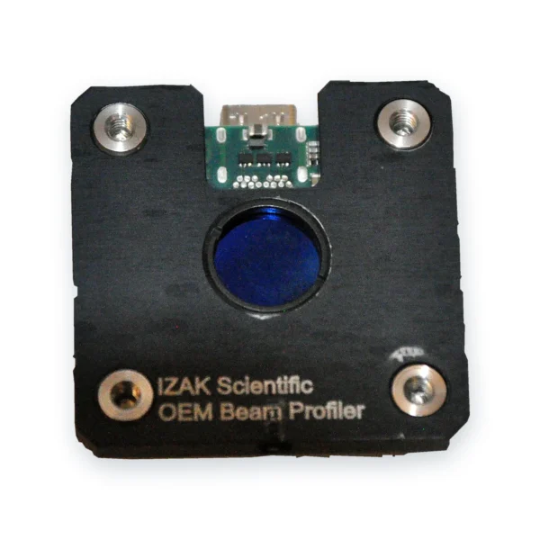 OEM · board levelOEM Board-Level Laser Beam ProfilersCompact global-shutter profilers for integration in your system or production station.View product →
 Laser acceptance testingTriBeam PrecisionBeam profile, power or energy and temporal pulse shape in one set-up.View product →
Other wavelengths: SWIR up to 2.05 µm, MWIR 1.5–5.7 µm and LWIR 7.7–12 µm. Need a custom measurement station? We design electro-optical systems →
What to send us for a recommendation
With these details an engineer can recommend the profiler and the measurement settings in one reply:
- Laser type and wavelengthe.g. fiber laser, 1070 nm
- Beam size and shapeexpected width at the measurement plane; Gaussian, top-hat or multimode
- Width definition you needD4σ, 1/e², FWHM or power content, and the tolerance
- Power or pulse energyCW power, or pulse energy and repetition rate
- What you will measurewidth only, M², pointing, uniformity
- EnvironmentR&D bench, OEM integration or production line
Frequently asked questions
QWhat is the D4σ beam width?
QIs D4σ the same as the 1/e² diameter?
QHow do I convert FWHM to the 1/e² diameter?
QWhy is my D4σ width much larger than the 1/e² width?
QWhat is the knife-edge 10/90 factor of 1.561?
QWhich beam width should I put in a specification?
References
- ISO 11146-1: Lasers and laser-related equipment — Test methods for laser beam widths, divergence angles and beam propagation ratios — Part 1: Stigmatic and simple astigmatic beams.
- ISO 11146-2: Part 2: General astigmatic beams.
- ISO/TR 11146-3: Part 3: Intrinsic and geometrical laser beam classification, propagation and details of test methods.
- ISO 13694: Optics and optical instruments — Lasers and laser-related equipment — Test methods for laser beam power (energy) density distribution.
Tzachi Sabati
CEO, IZAK Scientific
Physicist specializing in photonics and quantum technologies, with deep expertise in quantum sensors and advanced optical systems. Leads the Advanced Quantum Lab course at the Technion, bridging academic excellence with industry innovation. At IZAK Scientific, provides cutting-edge photonics-based solutions, developing customized inspection and sensing systems for R&D and production. Passionate about advancing quantum sensing applications and integrating novel technologies to meet industry needs.
