

In short
- The project: a prototype for research on a thermodynamic heat engine.
- Electronics: custom printed circuit boards and power supplies, and programmed microcontrollers.
- Integration: sensors, detectors, engines, pumps, generators, slip rings, microcontrollers and A/D converters in one system.
- Software and packaging: a LabVIEW application for command, control, live graphs and logging, in a neatly packaged prototype.
- From bench to box: a bench-top prototype first, then an enclosure and a dedicated PCB once the measurements were proven.
Project description
In this project we built a prototype for research on a thermodynamic heat engine. A research prototype has two jobs: it has to run the engine reliably, and it has to measure everything that happens inside it, so the researchers can see where the heat goes and how much of it becomes useful work.
From bench-top prototype to a packaged system
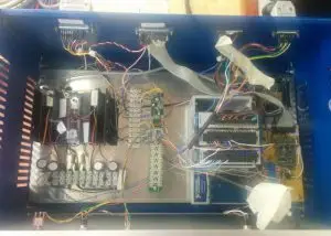
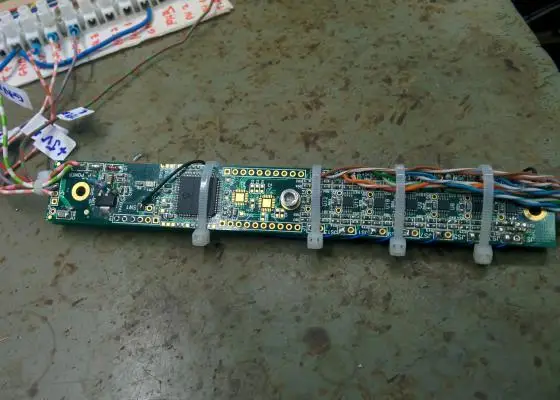
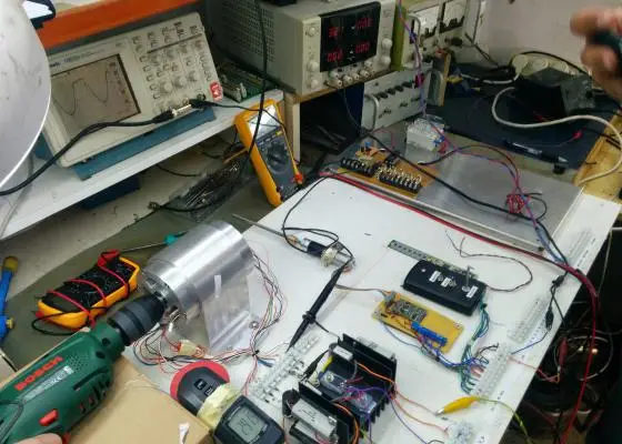
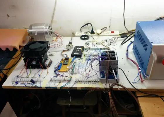
The prototype grew in stages, and the photos below follow that path. We started on the bench, with the engine, the sensors and the driver electronics open on the table, so the research team could change the set-up quickly and see every signal. Once the measurement chain and the control loop were proven, we moved the electronics into an enclosure and replaced the bench wiring with a dedicated printed circuit board, so the system runs as one safe, serviceable unit in the lab.
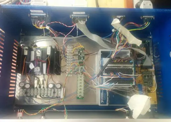
Moving from the bench to the box changes the hardware, not the science:
- Bench wiring becomes a dedicated PCB: fewer loose connections, repeatable assembly and cleaner sensor signals.
- The enclosure adds safety and access: hot parts and power electronics are covered, while connectors and service points stay reachable.
- The software stays the same: the LabVIEW application and the log format carry over, so data from the bench stage and the packaged stage can be compared directly.
What the development included
Developing and producing customized printed circuit boards and power supplies.
Programming the microcontrollers that run the engine’s local control.
Integrating sensors, detectors, engines, pumps, generators, slip rings, microcontrollers, A/D converters and more.
A graphical user interface for commanding and controlling the system, plus graphs and other physical values on screen, with every value written to a log file.
Elegant packaging that keeps the prototype safe, serviceable and ready for the lab.
Why measurement is built in from the start
The value of a heat engine prototype is in its data. Temperatures on the hot and cold sides, the heat put in, and the mechanical or electrical power that comes out decide the engine’s efficiency, and the efficiency is judged against the Carnot limit for the same temperatures. That is why the sensors, the A/D converters and the logging were designed together with the engine control, and why every value goes to a log file with a common time base.
The same approach applies to any electro-optical or electro-mechanical prototype: define what must be measured, then design the electronics and software around it. Our article on the right process for designing and developing a system explains the steps, and FPGA in your set-up covers when fast, deterministic control is needed. Heat pumps work the same cycle in reverse; see thermoelectric cooling and TEC testing.
How close is your engine to the Carnot limit?
Enter the hot- and cold-side temperatures, the heat input and the measured output power. The tool gives the Carnot limit, the measured efficiency and the share of the limit you reach. The values below are an example; enter your own.
Carnot limit = 1 − Tcold/Thot, with temperatures in kelvin (°C + 273.15). Efficiency = output power ÷ heat input. Heat rejected = heat input − output power, in steady state.
Prototype development at IZAK Scientific
We take research and product prototypes from the idea to a working, instrumented system: PCB design, embedded and LabVIEW programming, sensor integration and packaging. See our design and development services, or read how we build automated test stations in the IPL calibration case study.
Frequently asked questions
QWhat does a heat engine research prototype need?
QWhat is the Carnot limit?
QWhy use LabVIEW for a prototype?
Tzachi Sabati
CEO, IZAK Scientific
Physicist specializing in photonics and quantum technologies, with deep expertise in quantum sensors and advanced optical systems. Leads the Advanced Quantum Lab course at the Technion, bridging academic excellence with industry innovation. At IZAK Scientific, provides cutting-edge photonics-based solutions, developing customized inspection and sensing systems for R&D and production. Passionate about advancing quantum sensing applications and integrating novel technologies to meet industry needs.
Get new IZAK guides and tools by email
One short email a month: new technical articles, free calculators and product updates in laser measurement and electro-optics. No spam, unsubscribe anytime.
