

In short
- A camera pixel needs very little light. It saturates at a fluence of tens of nJ/cm². Most lasers deliver thousands to millions of times more, so a beam profiler almost always works behind an attenuator.
- Saturation does not look dramatic, but it changes the numbers. A peak only twice above full scale makes the D4σ width 7% too large and the FWHM 41% too large.
- Size the attenuation, do not guess it. Power or pulse energy, beam size, wavelength, exposure and pixel size give the optical density you need. The planner below does the arithmetic.
- Sample first, then absorb. At watt-level power, a wedge reflection takes away about 97% of the beam before any filter sees it. Use it near normal incidence, and keep every element polarization-neutral, so that both polarization planes are attenuated by the same factor.
Why a beam profiler needs attenuation
A camera-based laser beam profiler measures the beam by letting it fall directly on the sensor. Each pixel collects charge until its well is full. With a typical full well of about 10,000 electrons and an effective quantum efficiency of 30%, a pixel saturates at about 30 nJ/cm² at 633 nm. That is a very small dose.
Compare it with a modest laser. A 1 mW beam of 1 mm diameter has a peak irradiance of about 0.25 W/cm². In a 1 ms exposure the centre pixels receive about 250 µJ/cm², some 8,000 times more than they can hold. To bring the peak to 70% of full scale, the beam must be reduced by a factor of about 12,000, an optical density (OD) of 4.1. Watt-level CW lasers and millijoule pulses need OD 5 to 7.
Optical density is the base-10 logarithm of the reduction: OD 1 transmits 10%, OD 3 transmits 0.1%. Densities add when elements are placed in series, which makes it easy to build up the right value from several parts.
What saturation does to the measured width
A saturated image does not always look wrong. The beam still has a round shape on the screen, only its top is cut flat at the maximum grey level. The profile loses its peak, and every width that is measured relative to the peak grows. The table shows a simulated Gaussian beam whose true peak is above full scale by the factor in the first column.
| True peak / full scale | D4σ error | 1/e² clip error | FWHM error |
|---|---|---|---|
| 1.5× | +3% | +10% | +26% |
| 2× | +7% | +16% | +41% |
| 4× | +18% | +30% | +73% |
| 10× | +34% | +47% | +108% |
Simulation of a TEM₀₀ beam without noise, clipped at full scale; clip widths taken on the profile through the centre, relative to the clipped maximum.
The second-moment width reacts least because it uses the whole distribution, but even D4σ is off by several percent before the image looks obviously flat. Pass/fail limits and M² results inherit that error. Saturation also hides real structure: a hot spot in a multimode beam disappears into the flat top. More on how each width is defined in Beam width definitions: D4σ vs 1/e² vs FWHM.
Attenuation planner
Enter the laser, the beam size on the sensor and the camera settings. The planner calculates the dose on the brightest pixel, the optical density that brings it to your target level, and a practical chain of wedge reflections and ND filters.
Camera settings
Model: peak dose on the centre pixel, from the 1/e² diameter (Gaussian peak = 2P/πw², top-hat = P/πw²). Saturation dose = full well × photon energy ÷ quantum efficiency. Wedge reflection 3.4% per surface for fused silica near normal incidence. The quantum efficiency falls steeply towards the edge of a sensor’s spectral range; take it from the camera data at your wavelength.
Ways to attenuate, and when to use each
Coloured glass that absorbs a fixed fraction. Simple, cheap and insensitive to angle. The absorbed power turns into heat: at high power the glass warms, bends the wavefront and distorts the profile, and it can crack.
A thin metallic coating that reflects most of the light. Flatter over wavelength than absorbing glass and less heating, but the reflected beam must be dumped, and back-reflections can return to the laser.
An uncoated wedge reflects about 3.4% from its front surface; the wedge angle sends the back-surface reflection away. Each reflection is OD 1.47. Two in series give OD 2.9 while the main beam passes on to a dump or to the process.
For CW beams the exposure is a fine adjustment of the dose that costs nothing. Use it for the last factor of two to ten, not instead of optical attenuation. For pulsed lasers the exposure does not help once it is longer than the pulse.
For beams larger than the sensor, or for very high power, the camera images a scattering surface instead of taking the beam directly. The attenuation is then set by the scatter and the imaging optics.
A polarizer pair or a waveplate followed by a polarizer gives a continuous OD. Useful when the laser power changes over a wide range, but it works on one polarization plane only: the output is linearly polarized, and with an unpolarized or drifting laser both the transmission and the imaged profile change. Use it only with a stable, linearly polarized laser, and check that it does not alter the beam shape.
Polarization: attenuate both planes equally
A good attenuator reduces both polarization planes by the same factor. Many lasers are not purely linearly polarized: fiber, diode and multimode lasers are often unpolarized or only partly polarized, and the polarization can drift with temperature, power and fiber bending. In high-power solid-state lasers the two polarization components can even have different spatial profiles, because thermal stress birefringence in the gain medium affects them differently. An attenuator that favours one plane then does two things: the measured power density changes whenever the polarization changes, and the image is weighted towards one component, so the width, ellipticity and centroid you measure are not those of the whole beam.
- Absorptive ND filters at normal incidence or tilted by a few degrees: the same for both planes.
- Reflective ND filters: practically the same at small tilt; metal coatings become polarization-dependent at large angles.
- Wedge reflections: neutral below about 10° incidence, strongly polarization-dependent at 45° (table below).
- Polarizer-based variable attenuators: not neutral by design, because they pass one plane only.
The fraction a glass surface reflects depends on the angle of incidence and on the polarization. Near normal incidence the two polarizations behave the same. At 45° they differ by more than a factor of ten, so a polarization drift in the laser turns directly into an error in the measured power density.
| Angle of incidence | s-polarized | p-polarized | OD (s / p) |
|---|---|---|---|
| 0° | 3.4% | 3.4% | 1.47 / 1.47 |
| 5° | 3.4% | 3.3% | 1.47 / 1.48 |
| 10° | 3.5% | 3.2% | 1.45 / 1.49 |
| 45° | 8.0% | 0.64% | 1.10 / 2.19 |
Fresnel reflection of an uncoated fused-silica surface, refractive index 1.45.
Use wedge reflections at less than about 10° incidence. If the geometry forces 45°, use two wedges whose planes of incidence are at 90° to each other: each polarization is then reflected once as s and once as p, so both planes see the same total reflection (8.0% × 0.64% ≈ 0.052%, OD 3.29).
A quick check with a linearly polarized laser: place a half-wave plate before the attenuator and rotate it by 45°, which turns the polarization by 90°. The peak and the widths should not change by more than a percent or two; if they do, the attenuator chain is polarization-sensitive.
Keep the attenuator from changing the beam
- Place filters in the collimated beam. A thick filter in a converging beam adds spherical aberration and moves the focus.
- Tilt ND filters by a few degrees. Parallel filters form a cavity; their reflections overlap the main beam as ghosts and interference fringes.
- Put the strongest absorption last. Let the wedge and the reflective filters take the power, and use absorbing glass only where the power is low.
- Check the OD at your wavelength. ND values are usually quoted at one wavelength. In the near-IR many absorptive filters transmit noticeably more than their nominal OD.
- Keep optics clean and flat. Dust and surface errors on the last element before the sensor appear in the image as part of the beam.
- Dump every rejected beam. Wedge transmission, reflective-filter reflections and back-surface reflections must end in a beam dump, not on the bench or back in the laser.
Pulsed lasers: energy per frame decides
For a pulsed laser the sensor integrates every pulse that falls inside the exposure. When the pulse is much shorter than the exposure, shortening the exposure changes nothing; only the pulse energy, the number of pulses per frame and the optical density matter. At high repetition rates many pulses fall inside one frame, so the dose per frame is the pulse energy times that number.
Two quantities must stay within limits at the same time: the dose per frame on the sensor, and the average power on the attenuating optics. A 1 mJ pulse at 10 Hz is only 10 mW of average power, but its peak fluence on a 3 mm beam is about 28 mJ/cm². That is far below the damage level of good optics, yet it needs about OD 6.35 to keep the sensor out of saturation. Triggering, exposure and timing for pulsed beams are covered in How to profile a pulsed laser beam.
Damage: the sensor and the first optic
Saturation is reversible; damage is not. A focused beam, even of moderate power, can burn the sensor’s cover glass or the pixels themselves. Before the beam reaches the camera for the first time:
- Start with too much attenuationbegin at the highest OD you have, then remove filters one at a time while watching the peak level
- Never put the sensor at a focus without calculatingthe peak irradiance grows with the square of the reduction in beam size; a beam focused ten times smaller is a hundred times more intense
- Check the first optic’s ratingcompare the peak irradiance (CW) or peak fluence (pulsed) shown by the planner with the laser-induced damage threshold of the first element in the chain
- Block before you changeblock the laser while adding or removing filters, so the sensor never sees the beam with part of the chain missing
How to check that the image is not saturated
- Read the peak valuethe brightest pixel should sit below about 90% of full scale; most profiler software shows it, often as a histogram or a peak-level bar
- Add OD 0.3the peak should fall to half and the widths should not change beyond the frame-to-frame noise; if the widths shrink, the image was saturated
- Look at the profile, not the colour mapa flat top on the line profile through the centre is the signature of saturation
- Take a new backgroundafter any change of attenuation or exposure, record a dark frame with the beam blocked and subtract it
- Look for ghostsa faint second spot that moves when you tilt a filter is a reflection from the attenuator, not part of the beam
- Check polarization sensitivityturn the laser polarization by 90° with a half-wave plate before the attenuator; the peak and the widths should stay the same
The same rules apply when measuring at several planes for beam quality: the attenuation must keep the peak below full scale at the waist, where the beam is most intense. The M² measurement guide explains the full procedure, and the Gaussian beam calculator gives the beam size at each plane.
PDF · 6 pages
Take the checklist with you
- Wavelength-to-detector map, 0.3 to 12 µm
- Pixel-pitch and sensor-size rules with worked examples
- Pulsed vs CW, attenuation and production QA checklists
- A fill-in specification worksheet for your RFQ
IZAK products for this application
Every IZAK profiler is configured together with its attenuation: we size it to your power or pulse energy, beam size and wavelength.
 Beam profiling · 300–1100 nmUV–VIS–NIR Laser Beam ProfilersEight models from 1.2 to 67 MP; global-shutter models for pulsed lasers, with peak-level indication and ISO 11146 widths.View product →
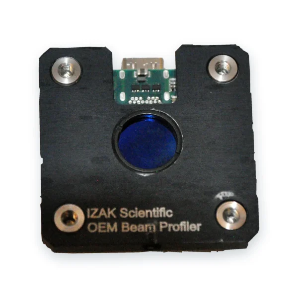 OEM · board levelOEM Board-Level Laser Beam ProfilersCompact global-shutter profilers for integration in your system or production station, with attenuation designed for the beam path.View product →
 Laser acceptance testingTriBeam PrecisionBeam profile, power or energy and temporal pulse shape in one set-up.View product →
Other wavelengths: SWIR up to 2.05 µm, MWIR 1.5–5.7 µm and LWIR 7.7–12 µm. Need a complete test station? See electro-optical system development.
What to send us for an attenuation design
With these details an engineer can recommend the profiler and the attenuation chain in one reply:
- Laser type and wavelengthe.g. fiber laser, 1070 nm
- Power or pulse energyCW power, or pulse energy, pulse width and repetition rate
- Beam size at the measurement planeand whether you need to measure at a focus
- Polarizationlinear, random or changing
- Space and geometrybench, OEM integration or production line; where the main beam must go
- What you will measurewidth only, M², pointing, uniformity
Frequently asked questions
QHow much attenuation does a laser beam profiler need?
QWhat is optical density (OD)?
QHow do I know if my beam profile is saturated?
QCan I reduce the exposure time instead of using filters?
QAbsorptive or reflective ND filters for high power?
QWhy should a wedge beam sampler be used near normal incidence?
QShould the attenuator work the same for both polarizations?
References
- ISO 11146-1: Lasers and laser-related equipment — Test methods for laser beam widths, divergence angles and beam propagation ratios — Part 1: Stigmatic and simple astigmatic beams.
- ISO 13694: Optics and optical instruments — Lasers and laser-related equipment — Test methods for laser beam power (energy) density distribution.
- ISO 21254-1: Lasers and laser-related equipment — Test methods for laser-induced damage threshold — Part 1: Definitions and general principles.
- EMVA Standard 1288: Standard for characterization of image sensors and cameras (quantum efficiency and saturation capacity).
Tzachi Sabati
CEO, IZAK Scientific
Physicist specializing in photonics and quantum technologies, with deep expertise in quantum sensors and advanced optical systems. Leads the Advanced Quantum Lab course at the Technion, bridging academic excellence with industry innovation. At IZAK Scientific, provides cutting-edge photonics-based solutions, developing customized inspection and sensing systems for R&D and production. Passionate about advancing quantum sensing applications and integrating novel technologies to meet industry needs.
