


In short
- Laser beam divergence measurement needs the far field. For a 3 mm beam at 1064 nm the Rayleigh range is about 5 m, so two widths taken 1 m apart on a bench understate the divergence by about 70%.
- Use the focal-plane method. Place a lens of focal length f in the beam and the profiler exactly one focal length behind it. The full-angle divergence is the measured spot width divided by f: θ = df / f.
- Measure at the focal plane, not at the smallest spot. For a diverging beam the two planes differ, and the smallest spot can read 85% low.
- Report it completely: full or half angle, the width definition (D4σ per ISO 11146), both principal axes, the wavelength and the focal length used.
What beam divergence is, and which number to report
Beam divergence describes how fast a laser beam grows with distance once it is far from its waist. Far from the waist the beam width grows linearly, and the divergence angle is the slope of that growth. It sets the spot size on a distant target, the size of every optic downstream, the coupling into a fiber and, together with the waist size, the beam quality.
Two choices change the number you report, so state both:
- Full angle or half angle. ISO 11146 uses the full angle Θ, which matches a diameter. Many laser datasheets quote the half angle. The two differ by exactly a factor of two.
- Width definition. ISO 11146 defines the beam width by the second moment of the intensity distribution, the D4σ width. For a perfect Gaussian beam this equals the 1/e² diameter; for real beams with wings or side lobes the two differ, and so do the divergences derived from them. Our complete guide to laser beam profiling explains the width definitions and how to convert between them.
For a beam of waist diameter d0, wavelength λ and beam quality factor M², the full far-field divergence is Θ = 4 M² λ / (π d0). The beam parameter product, BPP = (d0/2)·(Θ/2) = M² λ / π, is fixed for a given beam: a lens can trade waist size for divergence, but cannot reduce their product.
Why a direct far-field measurement is hard on a bench
The beam width grows as d(z) = d0·√(1 + (z/zR)²), where the Rayleigh range zR = π d0² / (4 M² λ). Within one Rayleigh range of the waist the beam barely grows; the linear, far-field regime starts at several zR. Two width measurements close to the waist therefore give a slope that is much too small. The table shows how far the far field is for typical lasers.
| Laser (example) | Waist d0 | M² | Full divergence Θ | Rayleigh range zR |
|---|---|---|---|---|
| 532 nm DPSS | 1.0 mm | 1.1 | 0.75 mrad | 1.3 m |
| 1064 nm solid-state | 3.0 mm | 1.3 | 0.59 mrad | 5.1 m |
| 1550 nm fiber collimator | 0.5 mm | 1.05 | 4.1 mrad | 0.12 m |
| 2.94 µm multimode | 4.0 mm | 5 | 4.7 mrad | 0.86 m |
| 10.6 µm CO₂ | 8.0 mm | 1.2 | 2.0 mrad | 4.0 m |
To keep a two-point measurement within about 1% of the true divergence, both planes must be more than about five Rayleigh ranges from the waist. For the 1064 nm example that means 25 m and more, and a beam that has grown to about 15 mm. Few labs have that path length, and a long path adds air turbulence, pointing drift and a beam larger than the sensor. The direct method works well only for strongly diverging beams, such as bare laser diodes and fiber outputs, where the far field begins within millimetres.
The focal-plane method for laser beam divergence measurement
A lens brings the far field to its back focal plane. In paraxial optics, a ray that enters a thin lens at angle α arrives at the back focal plane at height f·α, whatever its entry height. The intensity pattern at that plane is therefore a scaled copy of the far-field angular distribution, and the second-moment width obeys df = f·Θ exactly. This holds wherever the waist is before the lens, which is why ISO 11146-1 allows divergence to be determined with a focusing element as well as directly in the far field.
The procedure:
- Choose the lens. Pick a focal length that makes the spot at least 10 pixels wide (df = f·Θ) while keeping it under about one third of the sensor width. Use a clear aperture at least twice the beam diameter, so the lens does not clip the wings, and a low-aberration design such as an achromat or a correctly oriented plano-convex lens.
- Use the focal length at your wavelength. A lens specified at 587.6 nm in a common borosilicate crown glass is about 2% longer at 1064 nm: a nominal 500 mm lens becomes about 510 mm. Ignoring this biases the divergence by 2% and puts the sensor 10 mm away from the true focal plane. In the infrared, use a lens material made for that band and its focal length at the laser wavelength.
- Attenuate in the collimated beam, before the lens. The focused spot is intense. A 2 W beam focused to 0.29 mm reaches a peak irradiance near 6 kW/cm². A plate in the converging beam also moves the focus by t(1 − 1/n): a 3 mm plate with n = 1.5 shifts it by 1 mm.
- Place the sensor at distance f from the lens, measured from the lens principal plane, not from its mount. Do not hunt for the smallest spot.
- Measure the D4σ width along both principal axes, with background subtracted and the exposure well below saturation, and average several single frames.
- Compute Θ = df / f for each axis and report the conditions.
The same set-up also measures pointing stability: a change Δα in beam angle moves the spot centroid at the focal plane by f·Δα, while a parallel shift of the beam does not move it at all.
Worked example: 1064 nm laser with a 3 mm beam
A 1064 nm laser has a collimated output of 3.0 mm (D4σ) with M² = 1.3. The expected full divergence is Θ = 4 × 1.3 × 1.064 µm / (π × 3.0 mm) = 0.587 mrad, and the Rayleigh range is 5.1 m.
Direct attempt on the bench. Widths measured 1 m and 2 m from the waist are 3.057 mm and 3.222 mm. The slope is 0.165 mrad, 72% low. Even at 20 m and 40 m the result is 0.578 mrad, still 1.6% low.
Focal-plane method. With a 500 mm lens (focal length at 1064 nm), the spot at the focal plane is df = 500 mm × 0.587 mrad = 0.294 mm, or 53 pixels on a 5.5 µm pixel sensor. Θ = 0.294 mm / 500 mm = 0.587 mrad, with M² = 1.30 and BPP = 0.44 mm·mrad recovered from the 3.0 mm input width. For a 1% error budget the sensor must sit between about 13 mm before and 3.6 mm after the focal plane; the window is asymmetric because the true waist lies a few millimetres before f.
If the nominal 500 mm were used for a lens that is really 510 mm at 1064 nm, the sensor would sit 10 mm short of the focal plane and the computed divergence would be about 2% high. Small, but larger than the rest of the error budget.
Beam divergence calculator
Focal-plane mode converts a measured spot width into divergence, M² and BPP and gives the sensor placement tolerance. Far-field mode shows how wrong a two-point measurement is at your distances.
Engineering tool
Gaussian Beam CalculatorWaist, Rayleigh range, divergence and beam size at any distance, to plan the lens and sensor before you measure.Common divergence measurement mistakes
Measuring at the smallest spot instead of the focal planediverging beams
For a collimated beam the two planes almost coincide. For a diverging beam they do not. A 1550 nm beam with a 0.5 mm waist 1 m before a 200 mm lens has a true divergence of 4.14 mrad and a spot of 0.83 mm at the focal plane. Its smallest spot, 0.12 mm wide, is 49 mm further on; using it gives 0.62 mrad, 85% low.
Mixing half and full angles, or width definitionsfactor 2 and more
A half-angle 1/e² value compared with a full-angle D4σ specification looks like a 50% failure. State the angle convention and width definition with every result, and use the same definition on both sides of a pass/fail test.
Only one axisdiode, slab and astigmatic beams
Laser diodes can diverge several times faster in the fast axis than in the slow axis. Measure along the beam’s principal axes and report Θx and Θy. A single “diameter” of an elliptical spot hides the problem you need to see.
Clipping and poor baselinesecond-moment widths
D4σ widths weight the wings heavily. A lens aperture that clips the wings makes the divergence read low; uncorrected background and noise make it read high. Keep the spot under one third of the sensor, subtract a dark frame and use an analysis aperture around the beam.
Long exposures on a beam that movespointing jitter
At the focal plane, angular jitter becomes spot motion. A long exposure or an average image smears the spot and inflates the divergence. Take short exposures, compute the width frame by frame and report the centroid motion divided by f as pointing stability.
Divergence of infrared lasers
The method is the same at every wavelength; what changes is the detector and the optics. Pick the profiler family by wavelength: UV–VIS–NIR for 300–1100 nm, SWIR up to 2.05 µm, MWIR for 1.5–5.7 µm and LWIR for 7.7–12 µm. In the infrared, use a lens made from a material that transmits the band, with its focal length at the laser wavelength, and plan the attenuation for the full beam power before the lens. For a 10.6 µm CO₂ laser with an 8 mm beam and M² = 1.2, a 200 mm lens gives a focal-plane spot of about 0.40 mm, which suits a sensor with relatively large pixels. Pixel size against spot size is covered in small or large pixels for laser beam profiling, and the full caustic method for beam quality in how to measure M² with a beam profiler.
IZAK products for this application
A camera beam profiler with ISO 11146 second-moment widths at the focal plane gives the divergence along both axes, the centroid for pointing, and pass/fail limits for production test.
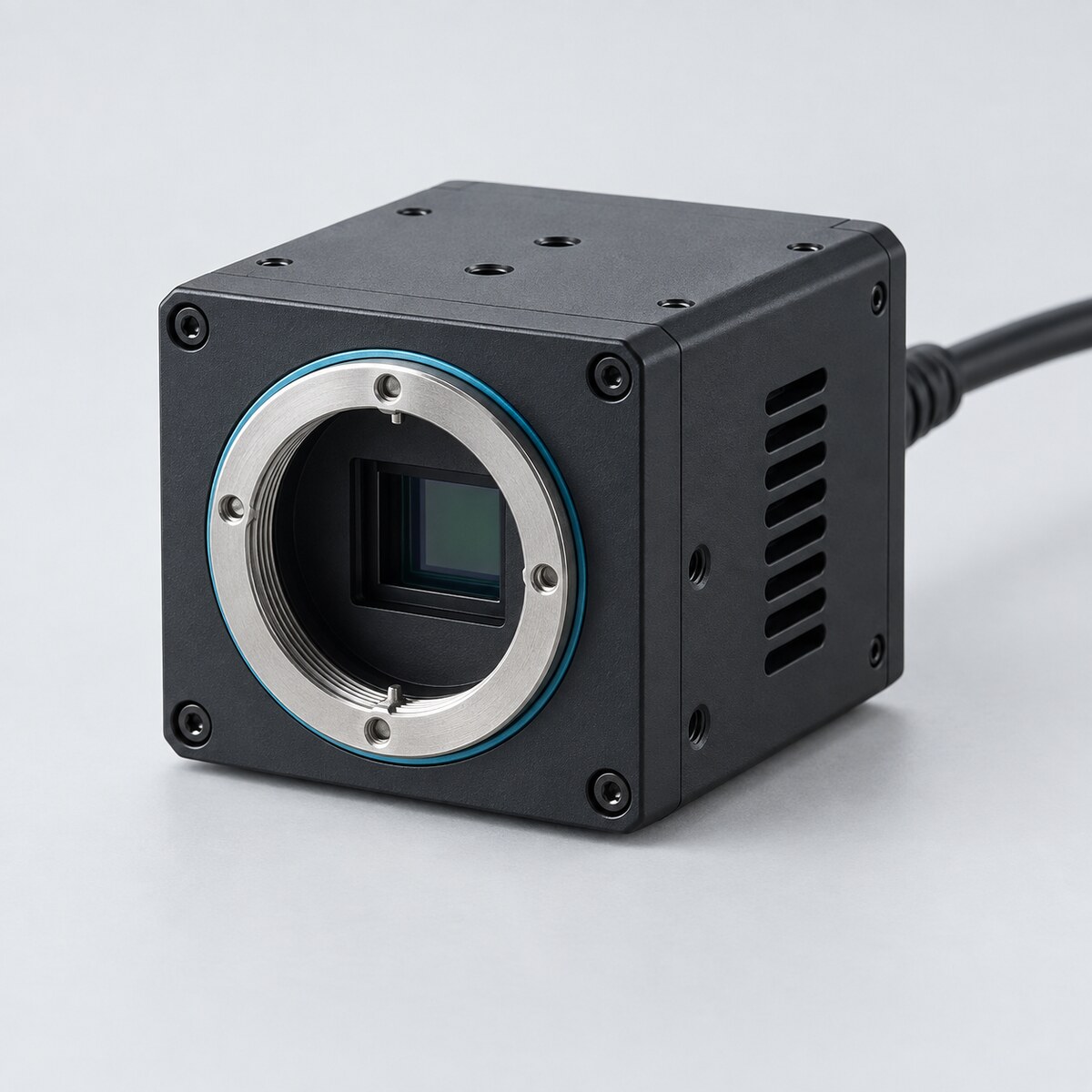 300–1100 nmUV–VIS–NIR Laser Beam ProfilersFor visible and near-IR lasers, including 1064 nm.View product →
 SWIR up to 2.05 µmSWIR Laser Beam ProfilersFor 1310 nm, 1550 nm and fiber lasers.View product →
 7.7–12 µmLWIR Laser Beam ProfilersFor CO₂ lasers at 9.3 and 10.6 µm.View product →
Building divergence or pointing tests into a product line? See the OEM board-level beam profilers or custom electro-optical test systems.
Frequently asked questions
QHow do you measure laser beam divergence?
QIs the divergence the same as the M² of the beam?
QWhy measure at the focal plane and not at the focus?
References
- ISO 11146-1:2021, Lasers and laser-related equipment — Test methods for laser beam widths, divergence angles and beam propagation ratios — Part 1: Stigmatic and simple astigmatic beams.
- ISO 11146-2:2021, Part 2: General astigmatic beams.
- ISO/TR 11146-3, Part 3: Intrinsic and geometrical laser beam classification, propagation and details of test methods.
Tzachi Sabati
CEO, IZAK Scientific
Physicist specializing in photonics and quantum technologies, with deep expertise in quantum sensors and advanced optical systems. Leads the Advanced Quantum Lab course at the Technion, bridging academic excellence with industry innovation. At IZAK Scientific, provides cutting-edge photonics-based solutions, developing customized inspection and sensing systems for R&D and production. Passionate about advancing quantum sensing applications and integrating novel technologies to meet industry needs.
