

In short
- In a Peltier module test, measure AC resistance, not DC resistance. A multimeter drives DC current, the module starts to pump heat and its Seebeck voltage adds to the reading. A four-wire AC measurement gives the true electrical resistance in seconds.
- The Harman method gives the figure of merit with the same wiring. Drive a small DC current, read the steady-state voltage and the instant voltage step when the current switches off: ZT = (VDC − VR) / VR.
- Z predicts cooling performance. ΔTmax ≈ ½ Z Tc², so a module with a low Z will not reach its datasheet ΔTmax.
- Set limits from golden samples. Heat loss in air makes the Harman method read low. Compare each module with known-good parts measured in the same fixture.
A Peltier module test must answer two questions before a thermoelectric cooler (TEC) is soldered into a laser diode package, an IR detector or a medical device: is the module electrically intact, and will it cool as the datasheet promises? Running every module to full ΔTmax in a vacuum chamber answers both, but it takes too long for incoming inspection or a production line. This guide shows how two fast electrical measurements, AC resistance and the Harman figure of merit, screen thermoelectric coolers in under a minute each. It includes the equations, a worked example with real numbers, a free calculator and the mistakes that most often produce false passes and false rejects.
What a Peltier module test should tell you
A TEC datasheet lists four performance parameters, all measured at a stated hot-side temperature Th, usually 27 °C or 50 °C, often in vacuum or dry nitrogen: the maximum temperature difference ΔTmax (at zero heat load), the maximum heat pumping Qmax (at zero temperature difference), and the current Imax and voltage Vmax at which ΔTmax is reached. It also lists the AC resistance (ACR) at a stated temperature, usually 25 °C, with a tolerance such as ±10%. Behind these numbers sit three material properties of the module: the Seebeck coefficient α, the electrical resistance R and the thermal conductance K. Together they define the figure of merit Z = α² / (R·K).
| Test | What it finds | Time per module | Where it is used |
|---|---|---|---|
| Visual and mechanical | Chipped ceramics, damaged leads, flatness, sealant defects | Seconds | Every module |
| Insulation resistance | Leakage between the circuit and the ceramic faces | Seconds | Every module when the faces touch metal |
| AC resistance (ACR) | Open or poor solder joints, cracked elements, shorts, wrong part | Seconds | Every module |
| Harman figure of merit (Z, ZT) | Degraded thermoelectric material, contact resistance, thermal shorts | Under a minute | Every module or a sample per lot |
| ΔTmax and Qmax | Real cooling performance against the datasheet | Minutes to an hour | Qualification and lot sampling |
| Thermal cycling and life test | Joint fatigue, delamination, resistance drift | Days to weeks | Qualification |
The two electrical tests in the middle of the table carry most of the screening load, because they are fast and they detect the defects that cause field failures. Our overview of TEC manufacturing variability and quality assurance explains where those defects come from and includes an operating-point calculator for choosing a module.
Why a TEC needs an AC resistance test
Connect a multimeter to a Peltier module and the reading drifts upwards for several seconds. The meter’s DC test current makes the module pump heat, a temperature difference ΔT builds up across it and the Seebeck voltage αΔT adds to the ohmic voltage I·R. The meter therefore reports R + αΔT/I, a value that depends on the test current, on how well the faces are cooled and on how long you wait.
An AC measurement avoids this. When the current reverses faster than the module can build up a temperature difference, the Peltier heating and cooling cancel within each cycle and only the ohmic voltage remains. Use a four-wire (Kelvin) connection so the lead and contact resistance, often tens of milliohms, do not add to a module resistance of one or two ohms. Practical test frequencies range from tens of hertz to about 1 kHz; the right value is the one above which the measured resistance stops changing for your module and fixture.
Two more points matter for a pass/fail decision. Module resistance changes with temperature, so let the module settle to room temperature after handling and record that temperature; datasheets state the ACR at a defined temperature, commonly 25 °C. And keep the test current small, so the measurement itself does not warm the module.
The Harman method: Z from two voltages
The Harman method, introduced in 1958, turns the “problem” of the drifting DC reading into a measurement. Drive a small DC current I through the module. After the temperature difference has settled, the voltage across the module is:
- Steady-state voltageVDC = I·R + α·ΔT = VR + VS
- Heat balance on the cold sidePeltier heat α·I·T equals the heat conducted back, K·ΔT, when Joule heating and losses are small. So ΔT = α·I·T / K.
- Figure of meritVS / VR = α²T / (R·K) = ZT, so ZT = (VDC − VR) / VR.
VR is read as the instant step when the current is switched off (or reversed): the ohmic part disappears at once, while the Seebeck part decays slowly as ΔT relaxes. Equivalently, VR is I times the AC resistance from the previous section. One wiring, one small current and two voltage readings give R, ZT and Z = ZT/T.
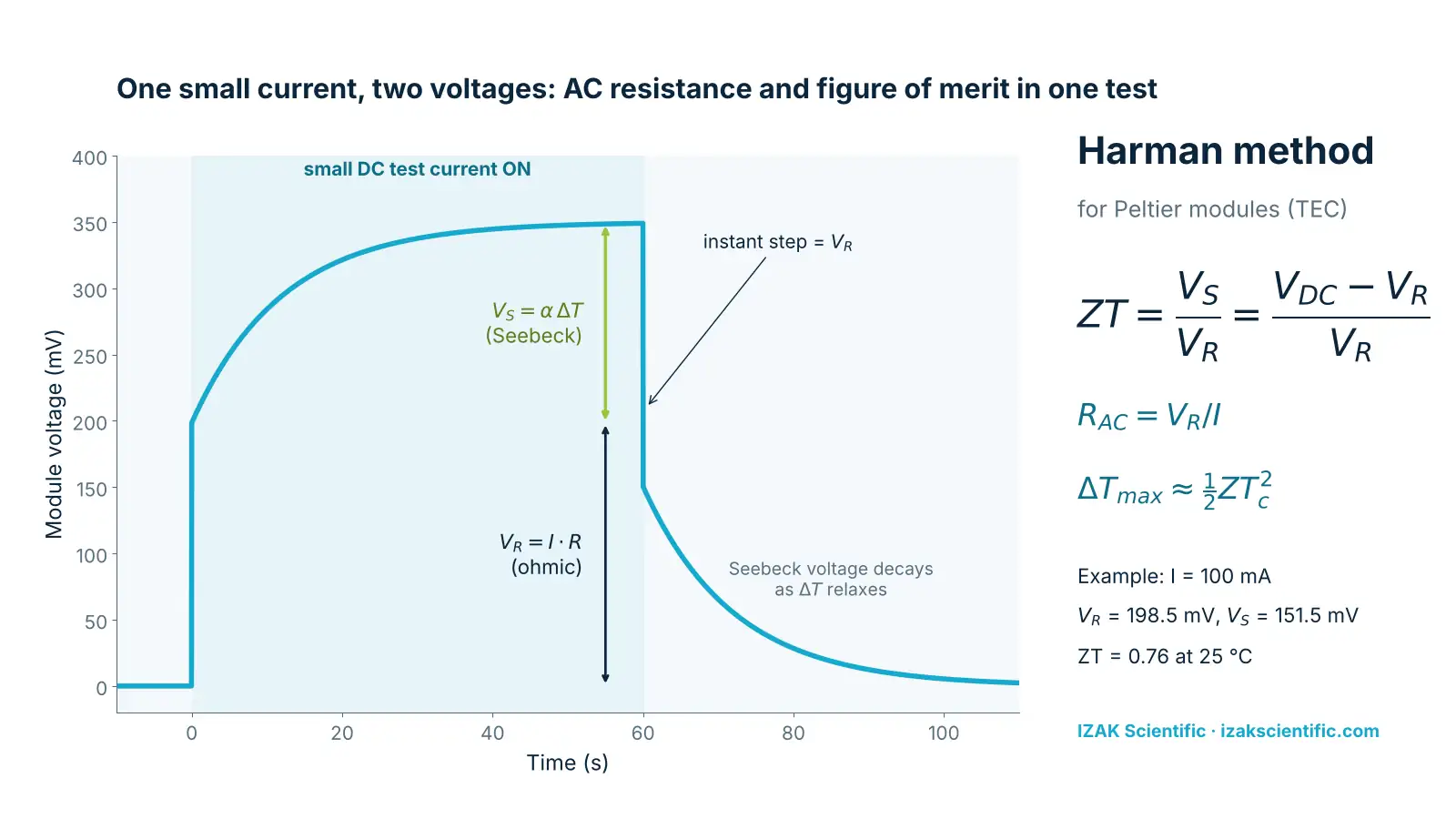
Why Z matters. For an ideal module, the largest temperature difference it can reach is ΔTmax = ½ Z Tc², where Tc is the cold-side temperature in kelvin. A module whose Z is 10% low will fall about 4.5 K short of a 70 K datasheet ΔTmax, which may be exactly the margin a cooled detector or a wavelength-stabilised laser diode needs. The same relation runs backwards: from the datasheet ΔTmax and Th, Z = 2ΔTmax / (Th − ΔTmax)², and with Vmax and Imax you also get the module α = Vmax/Th, R and K. The calculator below does both.
Conditions for a valid result. The derivation assumes all the Peltier heat returns through the module. In practice some leaks to the air, the leads and the fixture, and the measured ZT comes out low; published comparisons with heat-flow methods report Harman results 10–35% low in non-adiabatic conditions and up to about 40% low at atmospheric pressure. For screening this is acceptable as long as every module is measured the same way: suspend the module by its leads or on low-conductance supports, keep air still, use the same current and timing, and compare against golden samples. Keep the current low enough that Joule heating, ½I²R, stays at a few percent of the Peltier heat αIT or less.
TEC Harman test calculator
Enter the datasheet values and your Harman measurement. The tool returns the AC resistance, ZT and Z, compares them with the datasheet and predicts ΔTmax. Limits are a screening guide; set production limits from golden samples.
Datasheet
Harman measurement
Worked example: screening a 6 A module
Take a module whose datasheet gives ΔTmax = 70 K at Th = 27 °C (300.15 K), Imax = 6.0 A, Vmax = 15.4 V and ACR = 2.0 Ω ±10% at 25 °C.
1. Datasheet model. α = 15.4 / 300.15 = 51.3 mV/K. R = (300.15 − 70) × 15.4 / (300.15 × 6.0) = 1.97 Ω. K = 230.15 × 15.4 × 6.0 / (2 × 300.15 × 70) = 0.506 W/K. Z = 2 × 70 / 230.15² = 2.64 × 10⁻³ 1/K, so ZT ≈ 0.79 at 300 K. The derived R agrees with the nominal ACR within 2%, a useful sanity check of the datasheet itself.
2. Measurement. At 25 °C a 100 mA test current gives a steady-state voltage of 350.0 mV and an instant step of 198.5 mV at switch-off. R = 0.1985 / 0.100 = 1.985 Ω, 0.7% below nominal: pass. ZT = (350.0 − 198.5) / 198.5 = 0.763, Z = 0.763 / 298.15 = 2.56 × 10⁻³ 1/K, 97% of the datasheet value. The predicted ΔTmax at 27 °C is 68.6 K.
3. Is the test valid? The Seebeck voltage 151.5 mV corresponds to ΔT = 0.1515 / 0.0513 ≈ 3.0 K across the module, small enough not to change the material properties. Joule heating is I·R / (2αT) = 0.1985 / (2 × 0.0513 × 298.15) = 0.65% of the Peltier heat. Both conditions of the method hold.
4. A failing module. A second module from the same lot reads 236 mV ohmic and 387.5 mV total. Its resistance is 2.36 Ω, 18% above nominal: fail. The Seebeck voltage is unchanged at 151.5 mV, so the material still pumps heat, but ZT drops to 0.64 and the predicted ΔTmax to 61 K, because the extra resistance adds Joule heat at every operating current. A single high-resistance joint is the classic cause, and it is also where the module will fail first under thermal cycling. Load both cases into the calculator with the buttons above.
ΔTmax and Qmax: when you need the full thermal test
Electrical screening tells you the module is the module you bought. Qualifying a new supplier, a new module type or a new assembly process still needs a thermal test. Clamp the hot side to a temperature-controlled plate at the datasheet Th, place a small calibrated heater and a temperature sensor on the cold side, and test in vacuum or dry nitrogen to remove convection and condensation.
- ΔTmaxWith the heater off, raise the current until ΔT stops increasing. That ΔT is ΔTmax, the current is Imax and the voltage is Vmax.
- QmaxAt Imax, apply two or three heater powers and record ΔT. The heat load falls almost linearly with ΔT; extrapolate the line to ΔT = 0 to get Qmax.
- Cross-checkCompare the result with the ΔTmax predicted from the Harman Z of the same module. Agreement within a few kelvin validates the fast test as a production screen for that module type.
Once the correlation between the fast electrical test and the full thermal test is established on a qualification lot, production can rely on ACR and Z for every module and keep the thermal test for periodic lot sampling.
Building a TEC production test station
On a production line the measurements above become a sequence that runs per serial number: load the module, check insulation, measure ACR, run the Harman step, compare with limits, log and report. What makes the station reliable is not the formula but the fixture and the software: repeatable contacts, the same thermal environment for every module, timing that waits for a settled ΔT, automatic pass/fail against limits set from golden samples, and traceable records for each unit.
The IZAK TEC Tester is built for this job: an adaptable test bed for different TEC sizes, an integrated power supply, automated test software with pass/fail criteria, and results linked to each module’s serial number with quality-control reports. When a line needs a different sequence, more channels or integration with a factory system, IZAK control engineering builds the station in LabVIEW and, where timing matters, on FPGA; our article on using FPGA in electro-optics test set-ups explains when hardware timing pays off.
Common Peltier module test mistakes
The Seebeck voltage adds to the reading and the result depends on the current and the wait time. Use AC, four-wire.
Lead and contact resistance add tens of milliohms to a 1–2 Ω module, enough to move a part across a ±5% limit.
A module just handled or just soldered is not at 25 °C. Let it settle and record the temperature.
Joule heating breaks the Harman approximation and warms the module. Keep it at a few percent of the Peltier heat.
If ΔT has not settled, ZT reads low. Measure the time constant once per module type and wait several of them.
Heat loss in air biases ZT low. Set limits from golden samples measured in the same fixture, not from the datasheet alone.
IZAK products for this application
 TEC testTEC TesterAutomated TEC testing with pass/fail criteria, serial-number tracking and QC reports.View product →
 Test automationControl EngineeringCustom test stations and control software in LabVIEW and FPGA.View service →
Need a complete test system for thermoelectric or electro-optic components? See IZAK system design and development.
Frequently asked questions
QWhat is a normal AC resistance for a Peltier module?
QCan I test a Peltier module with a multimeter?
QWhat does the Harman method measure?
Tzachi Sabati
CEO, IZAK Scientific
Physicist specializing in photonics and quantum technologies, with deep expertise in quantum sensors and advanced optical systems. Leads the Advanced Quantum Lab course at the Technion, bridging academic excellence with industry innovation. At IZAK Scientific, provides cutting-edge photonics-based solutions, developing customized inspection and sensing systems for R&D and production. Passionate about advancing quantum sensing applications and integrating novel technologies to meet industry needs.
