


In short
- Use an FPGA when timing must be deterministic. Logic runs in parallel with fixed, nanosecond-scale delays, so control loops and timestamps behave the same way every time.
- Process the data next to the source. FPGAs filter, decimate, run FFTs and detect events at ADC rates that a PC cannot keep up with.
- The best fits in electro-optics: laser drivers and stabilisation, LiDAR and time-of-flight, dual-comb spectroscopy, adaptive optics, high-speed vision and quantum photonics (QKD, photon counting, feed-forward).
- Size the timing first. 100 ps of timing jitter equals 1.5 cm of range error. Use the calculator below to size TDC precision, sample rate and FFT length for a LiDAR project.
Field-programmable gate arrays (FPGAs) are ideal for electro-optical applications that need real-time precision, high-bandwidth control and deterministic behaviour. This article explains why, and walks through where FPGAs bring the most value in classical photonics and in quantum technologies, with examples from published research from the last five to seven years and from systems IZAK Scientific has built.
What an FPGA is and why it suits photonics
FPGAs are reconfigurable integrated circuits that let engineers build custom hardware logic. They contain configurable logic blocks (lookup tables and flip-flops), programmable interconnects, dedicated DSP cores and memory blocks. This architecture gives massive parallelism, deterministic timing with nanosecond-scale latency, and the flexibility to interface directly with fast ADCs, DACs and optical transceivers.
The building blocks are configurable logic blocks (CLBs), block RAM, DSP slices and high-speed I/O transceivers. Unlike a CPU, which executes instructions one after another, FPGA logic runs truly in parallel. FPGA designs are synchronous: every operation is clocked, so propagation delays are fixed and known, on the order of nanoseconds. The same input always produces its output after the same delay.
Timing jitter: why deterministic timing matters
Timing jitter is the fluctuation of an event’s timing around its ideal value, usually quoted as the standard deviation (RMS) of the timing error. In photonics, jitter widens or shifts laser pulses, blurs detector gating windows and degrades time-of-flight accuracy.
FPGAs reduce jitter because they bypass operating-system scheduling delays entirely, and because they can host custom time-to-digital converters (TDCs) and phase-locked loops (PLLs). A commercial FPGA-based time-interval analyser, for example, reaches 780 fs timing resolution with RMS jitter below 20 ps. Tapped delay lines built in the FPGA fabric can resolve intervals shorter than the base clock period. This is exactly what synchronisation tasks need, such as locking laser pulses to detector gates: an FPGA pulse monitor applies the same, repeatable delay every time.
Three benefits of FPGAs in electro-optics
Fixed, clocked delays and on-chip TDCs and PLLs give picosecond-class timestamps and repeatable triggers for lasers and detectors.
Filtering, FFTs and neural-network inference run at the ADC rate, with deterministic throughput. Closed-loop control in adaptive optics and spectroscopy runs at microsecond rates.
The same hardware can be re-programmed as the experiment or product changes, without a new chip. That makes FPGAs the standard platform for prototypes and small-series systems.
High-speed optical communication systems
In optical communication, FPGAs are the digital engine of transceivers and research prototypes for links running at tens of Gb/s. In short-reach PAM4 links, for example, an FPGA performs real-time pre-compensation and equalisation of the link’s nonlinearities.
Hu et al. (2024) demonstrated a 24.576 Gbit/s short-reach link: 14.7456 GBaud PAM4 over 20 km of fiber, with a 64-channel parallel multilayer perceptron on the FPGA performing digital pre-distortion. The bit-error rate stayed below the forward-error-correction (FEC) threshold. The authors describe FPGAs as ideal for high-speed optical data transmission.
FPGAs also handle carrier recovery, coherent demodulation, FEC and framing at 100 Gb/s and beyond. In commercial volume production ASICs take over these functions, but FPGAs remain the key tool for prototyping because they can be re-programmed. Other examples include a 4 Gb/s low-latency underwater optical link, where the FPGA handles half-duplex timing and fast transmit/receive turnaround, and visible-light and optical wireless communication, where the FPGA adapts the link in real time to changes in the channel and in ambient light.
LiDAR and time-of-flight ranging
FPGAs handle both sides of a LiDAR: signal generation (pulse and chirp timing) and signal processing (capturing the returns and computing distance).
Pulsed time-of-flight. Range follows from the round-trip time, R = c·t/2, so centimetre accuracy needs a timing precision of roughly 100 ps. An FPGA TDC timestamps both the departure of the pulse and the arrival of its echo.
FMCW LiDAR. A frequency-modulated continuous-wave LiDAR sweeps (chirps) the laser frequency. The beat between the outgoing and returning light gives the distance, and its Doppler shift gives the velocity. This needs heavy FFT processing, which suits FPGA logic.
Kim et al. (2020) built an FPGA-based FMCW processing engine that uses digital down-conversion to reduce the sampling rate, so a 256-point FFT replaces an 8192-point FFT. It achieved 3 cm range increments with about 3 cm RMS error, and a CFAR (constant false alarm rate) detector on the FPGA improved this to about 1.9 cm RMS. The whole chain (mixers, decimation filters, power estimation, FFT and peak detection) runs in FPGA logic and block RAM. It was verified on an SoC FPGA and handles the beat frequencies of targets up to 50 m away.

In a multi-channel chaos LiDAR, an FPGA synchronised a pulsed laser, controlled a MEMS scanning mirror and processed the chaotic returns into a real-time 3D point cloud. TDCs for single-photon LiDAR reach tens of picoseconds of resolution, and one FPGA experiment reported about 150 fs RMS synchronisation jitter. FPGAs are growing in importance for LiDAR, often in hybrid FPGA–ASIC or FPGA–SoC designs.
LiDAR timing and FPGA sizing calculator
Size the timing and processing before choosing the FPGA. Enter the timing jitter of your time-of-flight chain, the FMCW chirp bandwidth and duration, the maximum range and the FPGA clock. The tool returns the range precision, the FMCW range resolution, the highest beat frequency, the minimum ADC sample rate and the FFT length per chirp.
ToF precision = c·σt/2. FMCW resolution = c/(2B); beat frequency fb = 2R·B/(c·T); minimum real sampling rate = 2fb (Nyquist, before any down-conversion); FFT length = next power of two above fs·T. Down-conversion, as in the example above, lowers the sample rate and FFT size.
Ultrafast lasers and spectroscopy
Picosecond and femtosecond lasers, frequency combs and high-speed modulation all depend on fast, precise timing. Chen et al. (2020) built a real-time FPGA processor for dual-comb spectroscopy that uses computational coherent averaging, with a 7× improvement in random noise compared with offline averaging. Dual-comb data arrive at several MHz of interferogram rate, which is too fast for PC processing.
In laser stabilisation, the FPGA locks the repetition rate or the carrier-envelope phase using photodiode feedback and cavity actuators, correcting timing errors on every pulse at tens of MHz. In pulse shaping and optical arbitrary waveform generation, the FPGA drives high-speed modulators.
A real-time laser absorption spectroscopy sensor on an edge FPGA–SoC platform sampled at 10 kHz and ran a neural network on the device to deliver gas measurements at 62.5 Hz, tracking combustion dynamics up to 200 Hz. Typical applications include pump-probe experiments, ultrafast microscopy and spectroscopic process monitoring.
Adaptive optics and beam control
Adaptive optics (AO) corrects wavefront distortion with deformable mirrors or lenses, driven by a wavefront sensor. The corrections must be applied within sub-millisecond time frames.
Zhang et al. (2023) controlled laser jitter with a fast steering mirror, a camera and an FPGA module programmed in LabVIEW FPGA, and achieved a stabilised beam with a fast transient response. A general-purpose processor in such a loop might manage only a few to tens of Hz; the FPGA runs at kHz rates. Image-based control of this kind combines centroiding and correlation on the camera data with PID control.
A full AO loop reads the sensor, reconstructs the wavefront with a matrix–vector multiplication and sends commands to the actuators, all within microseconds. AO systems have been demonstrated at 1–2 kHz update rates for dozens of actuators. FPGA loops are deterministic, unlike PC-based loops, and parallel sub-aperture processing scales to future telescopes with thousands of actuators. At the Apollon petawatt laser, real-time wavefront stabilisation with a Shack–Hartmann sensor and a deformable mirror used a GPU controller, and FPGA or hybrid solutions are considered for a faster response.
Before closing any beam-stabilisation loop, it helps to know the beam itself: its centroid, width and pointing stability. A laser beam profiler gives those numbers directly.
Photonic image processing and high-speed vision
This covers the digital processing of optical images at high frame rates, sometimes combined with optical pre-processing. Laser scanning microscopes and OCT systems use FPGAs for real-time filtering, FFTs and corrections. Smart cameras compress, extract features and threshold on board.
The appeal is pixel-parallel processing: one million pixels at 1000 frames per second is one billion operations per second, which an FPGA pipeline handles comfortably. The same algorithms (centroiding, frame accumulation and neural-network inference) serve LiDAR point clouds, wavefront sensor images and quantum imaging. In a single-pixel camera, the FPGA controls a micromirror array and processes the single-pixel detector readings to reconstruct the image in real time. Other applications include real-time holography and high-speed tracking at thousands of frames per second.
Quantum photonics and quantum technology interfaces
Quantum experiments need deterministic, fast control and recording for single-photon detection and qubit operations. FPGAs form the backbone of many quantum control systems.
Quantum communication: QKD and photon counting
Quantum key distribution (QKD) needs the quantum transmission itself plus real-time classical post-processing: error correction (reconciliation), privacy amplification and authentication. Lu et al. (2023) implemented multidimensional reconciliation for continuous-variable QKD on a high-end FPGA, with 8-dimensional reconciliation coding and a throughput of 4.88 million symbols per second. Privacy amplification has been run on block sizes above 108 bits with an FPGA cluster.
In discrete-variable QKD (BB84), the FPGA generates the pseudorandom sequences that drive the modulators, timestamps single-photon avalanche diode or superconducting detector events with sub-nanosecond accuracy and controls detector gating. An underwater QKD demonstration (2021) ran the full BB84 protocol on a single FPGA: synchronisation, sifting, error correction and privacy amplification.
For photon counting, FPGA TDCs achieve 10–20 ps time bins, and a commercial FPGA-based instrument timestamps photons with about 20 ps RMS jitter. Real-time histograms and Hanbury Brown–Twiss (HBT) correlations run on the device.
Quantum sensing and metrology
In quantum sensing set-ups the FPGA coordinates lasers, detectors and feedback. Optical atomic clocks and interferometric sensors need nanosecond-precision laser timing, AOM chirps and conditional sequences. In NV-diamond magnetometers the FPGA modulates the microwaves and demodulates the fluorescence in real time, with lock-in detection that extracts weak signals (see our introduction to NV centers and Zeeman splitting).
Coincidence detection across channels inside a single FPGA gives tight, picosecond-level calibration between channels, which heralded photon sources and quantum LiDAR need (see understanding photon entanglement). In cavity QED, the FPGA adjusts the magnetic field or laser intensity based on photon counts faster than decoherence, within microseconds. Portable quantum sensors such as gravimeters and atomic clocks rely on FPGA or SoC controllers for compact, low-power operation.
Quantum computing interfaces and feed-forward control
FPGAs bridge classical control and quantum hardware: they generate pulses, read out qubits and apply feed-forward. Commercial quantum controllers are built on FPGAs with real-time branching logic. QubiC 2.0, an open-source qubit controller, runs on an RFSoC FPGA with a multi-core design, one core per qubit; pulse shapes are stored in FPGA memory and updated between pulses. Feed-forward latency is tens of nanoseconds, roughly one FPGA clock cycle plus the pipeline delay, and the system demonstrated conditional operations and multi-FPGA synchronisation.
In photonic quantum computing, an FPGA has controlled a high-speed tunable beamsplitter with sub-microsecond switching based on photon detection events, realising a linear-optics gate with feed-forward. The same feed-forward is at the heart of quantum teleportation. Synchronising the clocks of multi-channel DACs and ADCs to sub-picosecond skew is important for multi-qubit calibration and for photon interference.
Watch: real-time hit detection and laser control on FPGA
FPGA systems built by IZAK Scientific
We develop FPGA-based acquisition and control systems in LabVIEW FPGA and LabVIEW Real-Time, on industrial embedded controllers and single-board FPGA controllers. Three examples:
Real-time signal acquisition and analysis: acoustic emission system
Our acoustic emission system runs on an industrial embedded FPGA controller with a current-input module, a voltage-input module and several simultaneous-sampling modules for MHz-range acquisition. The FPGA performs digital filtering, hit detection and the calculation of amplitude, energy, rise time and duration for each hit. The data move through DMA channels to the real-time layer, which displays waveforms, histograms and scatter plots. The FPGA is paired with a LabVIEW Real-Time application.
Laser driver control system

Laser cooling and thermal management controller

Thermoelectric coolers are often the weak point of such a loop. Our TEC Tester characterises each TEC before it goes into the system. For the full development flow, from requirements to a tested system, see the right process for designing and developing an electro-optics system.
Free engineering tool
Gaussian Beam CalculatorPlanning the optics around your FPGA loop? Find the waist, Rayleigh range and divergence of your laser beam.IZAK products for this application
Instruments from our catalog that match the measurements and set-ups in this article.
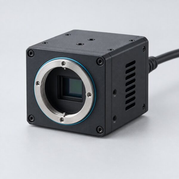 Laser metrologyLaser Beam ProfilersUV to LWIR families, packaged, OEM or software, with Test mode and reports.View product →
 Electro-optic driversHigh Voltage SwitcherDrive Pockels cells for Q-switching and pulse picking.View product →
Need something that is not in the catalog? We design custom electro-optical systems →
Sources
- Chen et al. (2020) – real-time FPGA processor for dual-comb spectroscopy with computational coherent averaging.
- Hu et al. (2024) – FPGA neural-network pre-distortion for a 24.576 Gbit/s PAM4 short-reach link over 20 km of fiber.
- Kim et al. (2020) – FPGA-based FMCW LiDAR processing engine with digital down-conversion and CFAR detection. Sensors, 20(22), 6676. Article.
- Zhang et al. (2023) – laser jitter control with a fast steering mirror, camera feedback and an FPGA loop.
- Lu et al. (2023) – FPGA multidimensional reconciliation for continuous-variable QKD at 4.88 Msymbols/s.
- QubiC 2.0 – open-source, FPGA-based multi-core qubit controller with feed-forward.
Frequently asked questions
QWhen should I use an FPGA instead of a PC or microcontroller in an optical set-up?
QWhat timing precision does a time-of-flight LiDAR need?
QHow are FPGAs used in quantum technologies?
Tzachi Sabati
CEO, IZAK Scientific
Physicist specializing in photonics and quantum technologies, with deep expertise in quantum sensors and advanced optical systems. Leads the Advanced Quantum Lab course at the Technion, bridging academic excellence with industry innovation. At IZAK Scientific, provides cutting-edge photonics-based solutions, developing customized inspection and sensing systems for R&D and production. Passionate about advancing quantum sensing applications and integrating novel technologies to meet industry needs.
