


In short
- A top-hat spreads the energy evenly. A Gaussian beam is brightest at the centre; a square top-hat has a flat plateau over a square area and steep edges.
- DOEs do the shaping. A diffractive optical element reshapes the phase of a clean single-mode (TEM₀₀) beam. Multimode or strongly diverging beams are better served by lens-array homogenisers.
- It pays off in processing, inspection and illumination: sharper edges, smaller heat-affected zones, repeatable dose and better use of the laser power.
- Verify, do not assume. A beam profiler shows the plateau, the edges and any residual hot spot, and turns uniformity (ISO 13694 flatness factor) into a pass/fail number.
Introduction: Gaussian versus top-hat
Most lasers emit a Gaussian beam: bright at the centre and gradually dimmer towards the edges. A top-hat (flat-top) beam, by contrast, has an almost constant intensity across its width and drops abruptly at the edges [1].
A square top-hat shapes that uniform region into a square. Instead of concentrating the energy in the centre, it delivers the same energy density over the whole spot. That uniformity matters in high-precision work that needs consistent illumination for quality control. In optical imaging and microscopy, flat-top illumination avoids a bright centre and dim edges, which would otherwise reduce efficiency or cause vignetting across a square field of view. The main uses are optical inspection, industrial laser processing and precision illumination.
Top-hat or Gaussian at the same power?
Compare a square top-hat of side a with a Gaussian beam of 1/e² diameter D carrying the same power. The tool shows the irradiance of each, how much of the Gaussian power lands inside the square, and how dark the edges and corners of the square would be with a Gaussian beam.
Gaussian peak = 2P / πw², with w = D/2. Power inside the square = [erf(a / (√2·w))]². Edge (middle of a side) = e−a²/2w² and corner = e−a²/w² of the Gaussian peak. Need the beam size after a lens or at a distance? Use our Gaussian beam calculator.
How top-hat optics is done
Top-hat beams are produced by beam-shaping optics placed on a standard laser output. Diffractive optical elements (DOEs) are micro-structured transmissive optics that reshape the phase front of the incoming beam. After propagation or focusing, the intensity redistributes into a flat-top profile, so a near-Gaussian input becomes a square spot with nearly uniform intensity [1]. This process is called beam homogenisation: irregularities and gradients are smoothed into a plateau, because the calculated diffraction pattern moves energy from the bright centre to the dimmer periphery. The output can be square, round or another tailored shape, always with sharp edges [1].
An ideal flat-top needs a high-quality input beam. DOEs work best with single-mode (TEM₀₀) lasers that have a clean Gaussian profile [1]. A single transverse mode is spatially coherent, so its diffracted parts interfere into a smooth, predictable pattern. Multimode or highly divergent beams suit diffractive shapers poorly; for them, multi-lens beam homogenisers such as lenslet arrays or multi-faceted mirrors are the usual alternative. The design depends on the wavelength, the input beam diameter and the focusing optics. A properly designed system delivers the target square size with nearly equal intensity across the plateau.
In summary, diffractive beam shapers redistribute the laser energy into a uniform square spot, provided the input beam matches the design.
Advantages of square top-hat beams
Using a square top-hat instead of the raw Gaussian beam brings four main advantages:
- Uniform intensity across the target. Every point in the illuminated area receives the same intensity, so a surface or workpiece is treated equally [1]. In laser curing or inspection, results stay consistent, with no bright spots and no weak corners.
- Improved precision and quality. The Gaussian central hot spot disappears, and the steep edge confines the working area, which gives sharper boundaries and higher accuracy. In cutting or ablation this means cleaner edges with minimal thermal damage beyond the cut line [5]. Micromachining studies report that flat-top beams reduce taper angles and improve edge definition and surface roughness compared with Gaussian beams [3][4].
- Minimised hot spots and heat-affected zones. A lower peak intensity avoids excessive energy density and material damage. With a Gaussian beam, the wings carry energy below the process threshold (wasted), while the core can exceed what is needed and enlarge the heat-affected zone [5]. A top-hat delivers just enough energy across the spot and then cuts off sharply, which reduces collateral heating such as burned cut edges or melting outside a weld seam.
- Consistent energy delivery and repeatability. Equal intensity across the spot gives the same energy profile on every run, without intensity variations across the spot that add variability. Less energy is wasted in Gaussian tails or in centre overshoot, which can allow faster processing or a larger treated area at the same laser power, and avoids overdriving the laser, which would shorten its lifetime or waste energy.
Applications
Square top-hat beams suit any task that needs uniform irradiation and precise control. Key areas include:
Optical inspection and imagingmachine vision · fluorescence · LIDT
Flat illumination helps machine vision, laser scanning and inspection. A square flat-top floods the field of view evenly, so any variation in the image comes from the object, not from the lighting. This is especially helpful on flat, reflective or patterned surfaces, where shadows or hot spots would hide detail. In fluorescence and multiphoton microscopy, a flat-top equalises the excitation across the view; in widefield multiphoton imaging, flat-top excitation removed the dark edges seen with Gaussian beams [6]. In laser-induced damage threshold (LIDT) testing, a well-defined fluence on the sample improves consistency and statistical confidence, and reduces measurement uncertainty in optical metrology [5].
Semiconductor processing and lithographyphotolithography · wafer inspection · annealing
Uses include photolithography, wafer inspection and laser drilling of circuits. Excimer lasers that expose photoresist are shaped into flat-tops with homogenisers or DOEs, so every chip on the wafer receives the same energy dose [7]. Consistent intensity over large rectangular areas gives uniform feature sizes. Laser direct writing and laser annealing gain better uniformity and fewer defects, and mask illumination and large-area exposure benefit as well.
Microscopy illuminationconfocal · multiphoton · widefield fluorescence
Flat-field illumination supports quantitative imaging in confocal, multiphoton and widefield fluorescence microscopy. When the beam is matched to the camera field of view, there are no dim corners. In multiphoton imaging, it equalises the nonlinear excitation probability across the imaging area, and in high-throughput and scanning cytometry it makes comparisons across the field more reliable. A uniform flat-top also reduces the variance of fluorescence measurements [5][6].
Laser machining and material processingcutting · drilling · scribing · welding
Cutting, drilling, scribing, welding and surface modification all benefit, especially when treating rectangular areas or raster-scanning the beam. Cutting gives cleaner, nearly vertical edges thanks to the sharp energy cut-off at the boundary; drilling gives more consistent hole diameters and depths; and micromachining (thin-film ablation, substrate patterning) gains feature uniformity. With no intensity tails, no part of the material is under-processed. In solar-cell film scribing, a flat-top gives more even ablation with less overlap between passes, and material marking benefits too. DOEs convert Gaussian fiber-laser or solid-state laser outputs into square or rectangular top-hats for higher throughput and quality [1][2].
Materials testing and metrologyLIDT · thermal tests
In LIDT testing of optical coatings, a uniform fluence across the test area gives a sharp damage threshold, instead of the gradual onset seen with a Gaussian beam [5]. In thermal tests such as thermal fatigue or ablation resistance, even heating avoids gradients that would skew the results: the sample gets a controlled, fair “bath” of laser energy [8].
Scientific R&D and experimental set-upsnonlinear optics · trapping · quantum optics · calibration
Optics and physics research often needs custom beam profiles. In nonlinear optics, flatter profiles improve frequency-conversion efficiency at high power [5] (see our introduction to nonlinear optics). In optical trapping, uniform intensity holds particles without unwanted gradient forces. In quantum optics, it gives uniform illumination of single-photon sources or sensors. Uniform beams also provide calibration targets with consistent irradiance for cameras, sensors and photovoltaic cells. Removing intensity variation across the sample as an experimental variable makes experiments possible that a non-uniform beam would make impractical.
Verifying the top-hat with the IZAK Laser Beam Profiler
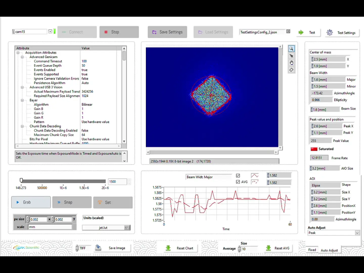
Producing a square top-hat is one challenge; verifying its profile and quality is another. The IZAK Laser Beam Profiler is a high-precision, camera-based system for UV, visible and infrared lasers (UV–VIS–NIR 300–1100 nm, SWIR up to 2.05 µm, MWIR 1.5–5.7 µm and LWIR 7.7–12 µm). It gives the quantitative data and visualisation needed to confirm that the DOE delivers the intended square output [9].
Key capabilities include beam size (width) under several definitions, beam shape and ellipticity, beam position and centroid, and intensity-distribution statistics. For a square top-hat, the X and Y full widths at half maximum (FWHM) should match; ellipticity and orientation checks confirm symmetry and squareness; and centre-of-mass and position data confirm the alignment in the optical system.
The profiler records the intensity at every point and produces 2D and 3D maps. Residual Gaussian bumps, hot spots and edge roll-off show up clearly in false-colour images and cross-section plots. The software quantifies uniformity with the flatness factor and plateau uniformity [5][7]: according to ISO 13694, a perfectly uniform beam has a flatness factor of 1.0 and a plateau uniformity close to 0 [7]. Engineers use these data to tune the DOE alignment or design, far more precisely than with burn paper.
For regular validation, automated testing applies user-defined pass/fail criteria, for example top-hat uniformity within ±5% of the mean intensity and output beam size within tolerance. A one-click test captures and analyses the beam in real time against the specification and produces a report with the measured profiles, numerical parameters and a pass/fail result. Raw beam images and data can be saved for traceability, which supports production QA of every unit’s beam. Models cover everything from small microscopy beams to large industrial beams, with high-resolution sensors. To understand the measurement basics, read The Essentials of Laser Beam Profiling.
| Check | What a good square top-hat shows |
|---|---|
| Size in X and Y (FWHM) | Equal widths in both axes, within the size tolerance |
| Ellipticity and orientation | Close to 1, with the square aligned to the process axes |
| Centroid and position | The spot centred where the process needs it |
| 2D and 3D intensity map | A flat plateau, no residual Gaussian bump, no hot spots, steep edges |
| Uniformity (ISO 13694) | Flatness factor close to 1.0; plateau deviation within tolerance, e.g. ±5% of the mean |
Is the plateau uniform enough?
Paste intensity readings taken across the plateau (from a profile line or ROI statistics), separated by commas or spaces, and set your tolerance. The tool checks every reading against the mean and gives the flatness factor (mean ÷ maximum, 1.0 for a perfect top-hat).
A simple acceptance test
- Check the input beamdiameter, centring and mode before the DOE
- Set the working distancethe plane the DOE was designed for
- Attenuatebring the spot into the sensor’s range without saturation
- Measure size and shapeX and Y widths, ellipticity, orientation, centroid
- Measure uniformityflatness factor, plateau deviation and edges against your limits
- Save the reportimages and data for traceability
Video demonstration
In our demonstration, a low-power green (visible) laser is expanded and sent through a diffractive top-hat DOE, and the resulting square beam is captured by the IZAK profiler camera. The software shows a false-colour intensity map with an evenly lit square plateau. The walkthrough identifies the edges and shows the 3D profile, with a flat top and steep edges. Live readouts include the X and Y beam widths, for example 3.0 mm × 3.0 mm if that is the design target. You can also see how changes in alignment and focus appear immediately in the profile. In short, the demo shows a Gaussian spot “squared off” by a DOE and verified by beam profiling.
Choose your set-up
Laser Beam Profiler configuration selectorPick the wavelength range, beam size and measurement set-up, and get the matching configuration.Conclusions
Square top-hat beams are an enabling technology for precision optics and industrial lasers. Uniform intensity with well-defined edges avoids the Gaussian hot spots that cause damage, uses the energy efficiently, and brings higher precision and better reliability. Realising these benefits takes both the right DOE and verification by beam profiling: the Laser Beam Profiler lets you see and measure the beam shape, confirm the target profile, and support tuning, qualification and field performance.
IZAK Scientific pairs custom beam shaping with robust beam profiling: tailored optical set-ups (for example, choosing the right DOE) through our electro-optics design and development service, and the measurement tools to prove the result. Beam uniformity and proper profiling underpin repeatable results. Contact us to request a DOE, a beam evaluation or a live demonstration.
Verification needs a detector matched to your laser wavelength, beam dimensions and power at the sensor. See the Laser Beam Profiler and the configuration selector to plan your measurement set-up. For other wavelengths, read how profilers support MWIR laser applications, and how AI analytics turns profiler data into production insight.
What to send us
With these details we can propose both the beam shaping and the measurement:
- Laser and wavelengthsingle-mode or multimode
- Input beamdiameter and divergence at the shaping optic
- Target spotsquare size and working distance
- Power or energyCW or pulsed, at the work plane
- Uniformity tolerancee.g. ±5% over the plateau
- Uselab, OEM integration or production QA
References
- Diffractive beam-shaper manufacturer – square-shape top-hat diffractive beam shaper, product description.
- Aspheric-optics manufacturer – “Beam shapers for square top hats in the focal point”, reference project with an optical-systems partner (advantages of a square top-hat profile).
- Diffractive-optics manufacturer – “Top hat laser beam explained” (flat-top beam characteristics and applications).
- Ramos-de-Campos, J. A., et al. (2020). Study of top-hat versus Gaussian beams in micro-structuring, showing improved quality with a top-hat. Micromachines, 11(2).
- Optics supplier application note – “Why use a flat-top laser beam?” (benefits and efficiency of flat-top beams).
- Salazar, et al. (2020). Flat-top beam illumination in multiphoton microscopy; a uniform beam eliminates vignetting. Journal of Biophotonics, 13(1).
- Beam-measurement instrument maker – “Flat-top beams and plateau uniformity calculations” (plateau uniformity and ISO 13694 beam-uniformity metrics).
- Optics supplier application note – flat-top beams reduce uncertainty in LIDT testing and improve fluorescence-imaging uniformity.
- IZAK Scientific – Laser Beam Profiler product page (specifications and features for beam measurement and analysis).
Frequently asked questions
QCan a DOE make a top-hat from a multimode laser?
QHow do I measure top-hat uniformity?
QWhy is the top-hat peak lower than the Gaussian peak at the same power?
Tzachi Sabati
CEO, IZAK Scientific
Physicist specializing in photonics and quantum technologies, with deep expertise in quantum sensors and advanced optical systems. Leads the Advanced Quantum Lab course at the Technion, bridging academic excellence with industry innovation. At IZAK Scientific, provides cutting-edge photonics-based solutions, developing customized inspection and sensing systems for R&D and production. Passionate about advancing quantum sensing applications and integrating novel technologies to meet industry needs.
