

In short
- The semiconductor sets the colour. The bandgap fixes the photon energy and so the wavelength: λ [nm] ≈ 1240 / Eg [eV]. Practical LEDs run from the deep UV (about 250–280 nm) to the near-IR (850 and 940 nm are the common IR choices).
- A bare LED is a Lambertian emitter: I(θ) = I₀ cos θ, a 120° wide beam. Lenses and reflectors, single or multi-element, reshape it for spot, automotive or stage lighting.
- Heat is the main enemy. Light output drops roughly exponentially with junction temperature and the wavelength shifts, so thermal design decides efficiency, colour stability and lifetime.
- Know the limits: LEDs excel at efficient, compact, spectrally controlled light, but very high output, sun-like broad spectra and long-wave IR are often better served by other sources.

Introduction
Light-emitting diodes (LEDs) are central to semiconductor-based lighting, from general illumination to sophisticated optical devices. For engineering managers and professionals, understanding the physics and engineering principles behind LEDs is essential to designing products that perform as intended. This article covers the optical properties of LEDs from the UV to the IR, their beam characteristics and optical design, thermal management and the applications where LEDs fit, and where they do not, linking the physics to performance and quality.
Optical properties and wavelength considerations
LEDs emit across a wide range, from the ultraviolet (UV) to the infrared (IR), which makes them suitable for many applications. The wavelength of an LED is set by the energy of the photons it emits, E = hν = hc/λ, and that energy is in turn set by the bandgap of the semiconductor.
Commercial UV-C LEDs based on AlGaN reach down to roughly 250–280 nm; 265 nm is a common choice for germicidal use. Shorter wavelengths are limited by material absorption and the availability of suitable wide-bandgap semiconductors, and they are hard to reach with enough power and efficiency. UV LEDs are used mainly for sterilisation and analytical work.
Near-IR LEDs at 850 and 940 nm are used in remote controls, surveillance illumination, sensing and short-range telecommunications. GaAs-based structures cover this range. Longer-wavelength IR LEDs exist, but their efficiency and output fall as the wavelength grows.
The maximum wavelength an LED can emit is set by the bandgap of its semiconductor:
Eg = hc / λ ⇒ λ [nm] ≈ 1240 / Eg [eV]
Longer wavelengths need smaller bandgaps, which brings challenges in efficiency and thermal stability: with a smaller bandgap, more carriers are thermally excited and more of them recombine without emitting light. At the other end, shorter wavelengths need wider-bandgap materials that are harder to grow and dope well, which is why deep-UV LEDs are still far less efficient than blue or red ones.
LED beam characteristics and optical design
Optical design for LEDs must account for the natural emission pattern of the chip and for the ways engineering can change it to suit the application.
Natural emission pattern
A bare, flat LED chip is close to a Lambertian emitter. Its intensity follows
I(θ) = I₀ · cos θ
where I₀ is the on-axis intensity and θ is the angle from the axis. The intensity halves at 60°, so the full beam angle at half maximum is 120°. Such a wide pattern is ideal for diffuse lighting but less suitable where focused light is needed: only a quarter of the flux of a Lambertian LED falls within ±30° of the axis.
Enhancing beam quality with optics
Lenses and reflectors reshape the emission pattern for targeted applications:
Single-LED lensesone chip, one lens
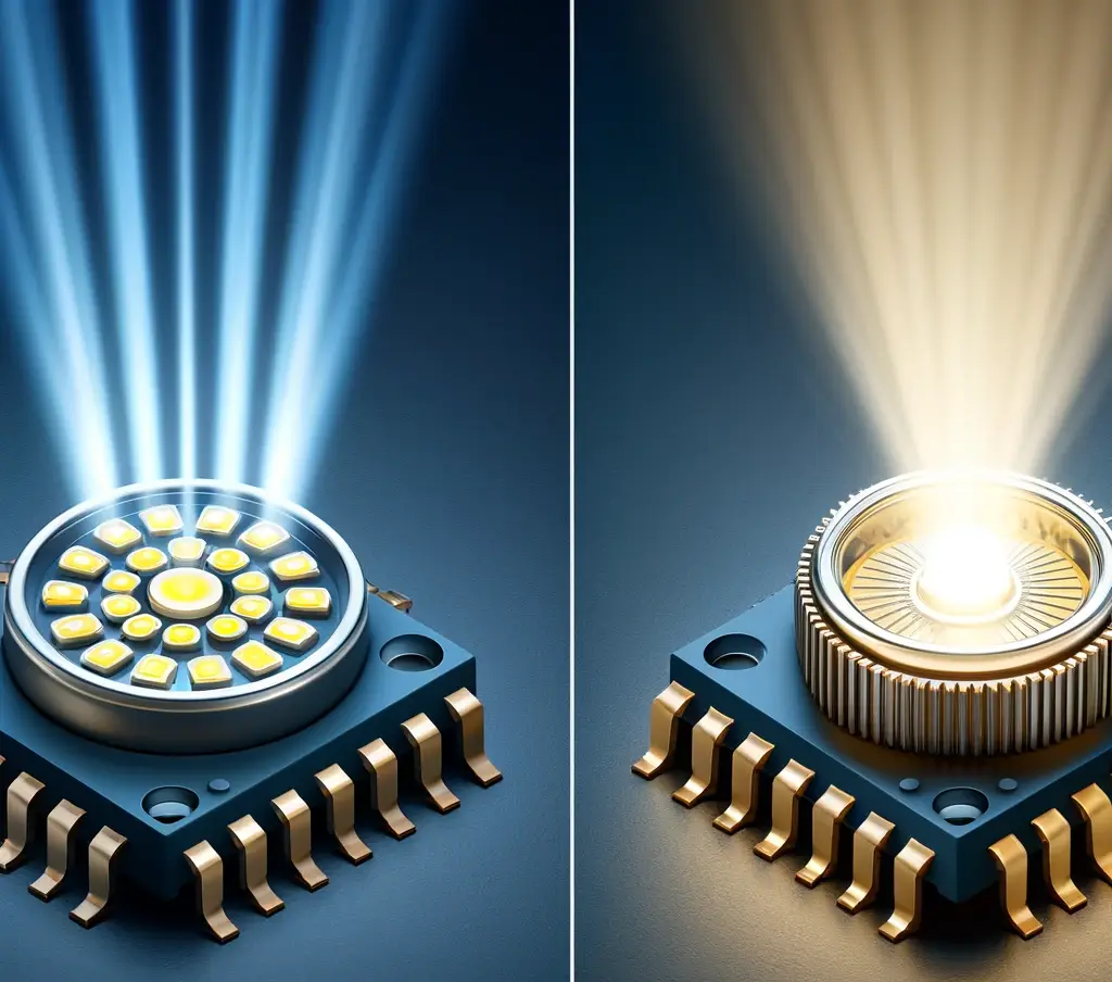
A primary or secondary lens collects the light from a single LED chip and directs it into the required angle, optimising the output and focus. Total-internal-reflection (TIR) optics combine refraction and reflection to collect even the wide-angle rays.
Multi-element lensesarrays and multi-chip sources
For LED arrays or multiple chips, multi-element optics combine the light into a single directed beam, as in automotive headlights and stage lighting.
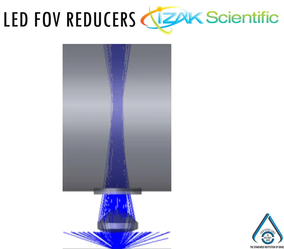
FOV reducersfor measurement and inspection
In test and inspection systems, an optic that narrows the field of view lets a detector look at one LED among many on a board without crosstalk from its neighbours.
LED photon energy, beam and thermal derating calculator
Enter the LED’s peak wavelength, the beam half-angle you need, the junction temperature and the LED’s characteristic temperature T₀. The tool returns the photon energy (and the bandgap it implies), the share of a bare Lambertian LED’s flux inside your cone, the ideal on-axis gain of a lossless optic that puts all the flux into that cone, and the light output at that junction temperature relative to 25 °C.
Model: E = hc/λ; Lambertian flux inside ±θ = sin²θ; ideal gain = 1/(2(1 − cos θ)), the average intensity of a uniform cone over the on-axis intensity I₀ = Φ/π of the bare LED; output Φ(Tj)/Φ(25 °C) = exp(−(Tj − 25)/T₀). Take T₀ from the LED’s flux-versus-temperature curve; red and amber LEDs usually have a much lower T₀, and so a stronger drop, than blue and green ones. Real optics lose 10–20% and do not produce a perfectly uniform cone.
Thermal management in LED systems
Thermal management is crucial in LED design because LED performance depends strongly on temperature.
Temperature effects on efficiency and spectrum
Both the efficiency and the spectral output of an LED change with temperature. Over the normal operating range, the light output is well described by an exponential with a characteristic temperature T₀:
η(T) = η(Tref) · e−(T − Tref)/T₀
Efficiency falls as the temperature rises, mainly because non-radiative recombination increases and, in some material systems, carriers escape from the active region. At the same time the bandgap shrinks, so the peak wavelength shifts to longer wavelengths, by a few hundredths to about a tenth of a nanometre per kelvin depending on the material. For colour-critical products this shift can matter as much as the loss of output. The junction temperature can be estimated in operation from the forward voltage or from the spectrum, as described in LED Inspection Part 1: Integrating Sphere.
Regulation strategies
Advanced cooling techniques and materials, such as graphene-based heat spreaders, are being explored to improve heat dissipation. Good thermal design, from the chip attach and the board through the heat sink to active cooling where needed, keeps the junction temperature low and stable. That preserves performance, keeps the wavelength stable and extends the LED’s lifetime. Thermal management is a cornerstone of LED system design.
Applications and limitations
The choice of LED technology depends on the required intensity, directionality and spectral quality. LEDs are versatile, but they are not the ideal solution for every lighting need.
Environmental monitoring, medical imaging, plant growth, low-energy lighting and commercial lighting. The strengths: spectral control, high efficiency, fast switching and compact integration.
Current materials may not meet the need for very high output in a small étendue, very precise or very broad spectra, or long-wavelength IR. Extremely high-power applications may need lasers or lamps.
Broad, continuous, sun-like light is still better served by halogen lamps, or, for pulsed UV-to-IR light, by xenon flash lamps such as the PXL pulsed xenon lamp module.
Conclusion
A sound understanding of LED physics, from the bandgap and the emission pattern to thermal behaviour, supports better product design and opens new applications in high-efficiency, precision lighting. As LED technology evolves, engineering leaders who master its operation and design can use it to the full and advance both commercial and technical goals.
To verify what you designed, measure it: total flux and spectrum in an integrating sphere, colour and position on the production line with the IZAK LED tester, and full spectra with the multi-channel spectro-radiometer. For the basics of the units involved, read The Basics of Light Measurement, and for a production QA example, Radiometry and LED Quality.
References
- Kittel, C. (2005). Introduction to Solid State Physics. John Wiley & Sons.
- Pankove, J. I. (1971). Optical Processes in Semiconductors. Dover Publications.
- Holonyak, N., & Bevacqua, S. F. (1962). Coherent (visible) light emission from Ga(As1−xPx) junctions. Applied Physics Letters.
Frequently asked questions
QWhat sets the wavelength of an LED?
QWhat is the beam angle of a bare LED?
QHow does temperature affect LED output?
Tzachi Sabati
CEO, IZAK Scientific
Physicist specializing in photonics and quantum technologies, with deep expertise in quantum sensors and advanced optical systems. Leads the Advanced Quantum Lab course at the Technion, bridging academic excellence with industry innovation. At IZAK Scientific, provides cutting-edge photonics-based solutions, developing customized inspection and sensing systems for R&D and production. Passionate about advancing quantum sensing applications and integrating novel technologies to meet industry needs.
