


In short
- What an LED checker does. It verifies the position, color and function of every LED on a PCB or indicator panel with an imager, a lens and recognition software.
- Three ways to embed it. As an API (DLL) inside your own tester, combined with other checks such as temperature and power, or as a standalone tester application.
- Learn once, test every board. A JSON configuration per board type; each test writes a CSV result.
- No fibers. The imager sees the whole board in free space, so there is nothing to connect and disconnect per board.
What is an LED checker?
An LED checker is a system that verifies the position and color of the LEDs on printed circuit boards (PCBs) and in the indicator buttons of electronic devices. Demand for LEDs has grown sharply over the past decade because they are efficient, cost-effective and durable, and with it the number of LEDs that must be checked on every product.
The checker identifies LED color with an imager, an optical lens and API software. Recognition combines diffuse-light imaging, which tells many colors apart, with a machine-learning algorithm. Color is sensed through color-sensitive filters over the imager’s pixel array, which evaluate the color of the emitted light. The solution is an imaging system, API software with sample code for common test environments, and, if you need it, a ready application.

Why do LEDs need extra attention in production control?
Besides lighting, LEDs are used as indicators in almost every electronic device. Because each color carries a meaning, correct color and placement matter when the device is built. A PCB can carry many LEDs, so the circuit must be tested for correct LED use: position, function and color.
Manufacturers therefore need a reliable, efficient LED control solution that confirms:
- Every LED works.
- The LEDs work correctly in each power option.
- The LEDs emit the correct color, and light in the correct order.
- The LED configuration is correct: the right LED in the right place.
How can an LED checker be embedded in an existing production line?
The LED checker software is an API (a DLL file) that you integrate into your standalone or automated tester application.
The LED test can run alongside other detection elements in the same station, such as temperature and power checks.
The software is also supplied as a standalone tester application, for lines that do not have their own test software.
Whichever way you embed it, the imager must see the whole board with enough pixels on every LED. The tool below checks that before you choose an imager and lens.
Will the imager resolve every LED on your board?
Enter the board size, the imager resolution, the smallest LED and the tightest LED pitch. The tool computes the field of view, the pixels on each LED and in the gap between neighbours, and the lens focal length for your working distance.
Model: field of view = board size × (1 + margin); resolution = the larger of FOV width ÷ horizontal pixels and FOV height ÷ vertical pixels (mm per pixel); pixels across LED = LED size ÷ mm per pixel; gap = (pitch − LED size) ÷ mm per pixel. Lens (thin-lens): magnification m = sensor size ÷ FOV (the limiting axis), f = m × WD ÷ (1 + m). Guide values: at least 5 pixels across each LED and 3 pixels between neighbours for reliable position and color; choose the nearest standard lens at or below the computed focal length.
Benefits of the LED checker
The system is simple to operate. Its functions recognize LED position, color and working status on the PCB:
- Open / close cameraCapture an image of the board, or load an existing image file from a path instead of a live camera.
- Learn a new configurationEach PCB type has its own LED layout, held in a JSON configuration file. Once the API learns and saves the layout, a whole batch of boards with that layout can be tested.
- TestAssess all the LEDs on the PCB and write the results to a .csv file.
Most LED checkers use optical fibers to detect color. IZAK Scientific’s LED color recognition API does not. With fiber-based testers, each PCB must be connected to and disconnected from the fibers, which is slow and tedious. The imager-based approach removes that step and stays simple to use. For a step-by-step look at learning, ROIs and matching grades, read LED tester of color and position: how does it work?
Watch: the LED tester checking colour and position
Customer story
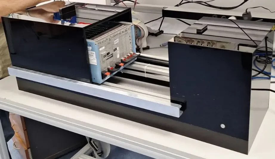
A global manufacturer of semiconductor-equipment subsystems bought an LED color and position tester from IZAK Scientific after earlier successful projects, for our expertise and fast delivery. They needed to test several PCB types, each with a few LED configurations. IZAK supplied a DLL API for the LED tester with a ready C integration example, which the customer integrated into its own tester software, and a tester box with an imager, optics and relays as a complete system.
What the customer said
“A smart, easy-to-learn machine-learning tool that learns a new PCB in a few minutes and allows quick testing in a free-space configuration.”“We received fully customized service and support from the IZAK team during integration. This was one of several projects with IZAK, and the team was professional and delivered on time.” Moshe Aizler, Testing Development Manager, Automation & Control Solutions, MKS InstrumentsRead next: LED tester: who needs it? and LED and shape inspection systems for high-volume production. Need a custom station? See our electro-optical system design and development.
Frequently asked questions
QHow do I integrate an LED checker with my existing tester?
QWhat imager resolution do I need for LED testing?
QWhy test LEDs with an imager instead of optical fibers?
Tzachi Sabati
CEO, IZAK Scientific
Physicist specializing in photonics and quantum technologies, with deep expertise in quantum sensors and advanced optical systems. Leads the Advanced Quantum Lab course at the Technion, bridging academic excellence with industry innovation. At IZAK Scientific, provides cutting-edge photonics-based solutions, developing customized inspection and sensing systems for R&D and production. Passionate about advancing quantum sensing applications and integrating novel technologies to meet industry needs.
