Optical system design · Project examples

Optical System Design Projects: Design, Build and Test

Real optical and electro-optical projects, from the first requirement to a tested system and a report you can file.

Each project on this page started with a measurement problem: light that had to reach a slit, a fiber or a detector, a beam that had to be uniform, or a spectrum that had to be measured in several bands at once. We show what the problem was, what we designed and how we proved it works. Most of these projects run on, or led to, the measurement instruments we make ourselves.

ISO 9001:2015Optics + opto-mechanicsPrototype and testUV to LWIR
IZAK multi-channel spectro-radiometer with three telescope channels on a common boresight
Multi-channel spectro-radiometer: three telescope channels, one boresight, one software.

Project description

How a design-and-test project runs

The subject can be an optical component, an optical device, a sensor or a light source. The steps are the same, and each one ends with something you can review.

  1. Requirement and subjectWe define what the component, device, sensor or light source must do, under which conditions, and which numbers prove it.
  2. Device and technology reviewWe compare the available devices and technologies against the requirement and recommend the best fit for performance, cost and supply.
  3. Design of experimentsWe plan how each function will be measured: set-up, reference, sample size, environment and the expected uncertainty.
  4. TestingWe run the tests in our lab with calibrated instruments and our own beam profilers and spectro-radiometers, and record every result.
  5. Report for your DHFA complete report of method, set-up, raw and analysed results and conclusions, ready for your Design History File.

See our optical system design method, step by step

Project examples

Problems we solved, and how

Six short project stories. Each one shows the challenge, the design decision that solved it and the instrument or product it connects to.

Optical layout for coupling light into a spectrometer slit

Spectroscopy

Coupling light into a spectrometer slit

Challenge
A spectrometer only sees the light that passes its narrow entrance slit at the right angle. Light lost at the slit is signal lost for the whole measurement.
What we did
We set the objective first, then designed relay optics that image the source onto the slit and match the spectrometer’s acceptance angle, so the light fills the slit without overfilling the grating.
Where it led
The same approach is used in every channel of our spectro-radiometers.
Spectro-radiometer
Examples of coupling, decoupling and sampling light to and from optical fiber

Fiber optics

Coupling, decoupling and sampling light in fiber

Challenge
Coupling efficiency into a fiber depends on the numerical aperture of the beam and of the fiber, on the spot size and on alignment. A small mismatch costs a large part of the power.
What we did
We analysed how the light behaves at each interface, matched NA and spot size, and designed couplers, collimators and taps that sample a known fraction of the light for monitoring.
Where it led
Fiber transmission and inspection testers for fiber production lines.
Optical fiber inspection tester
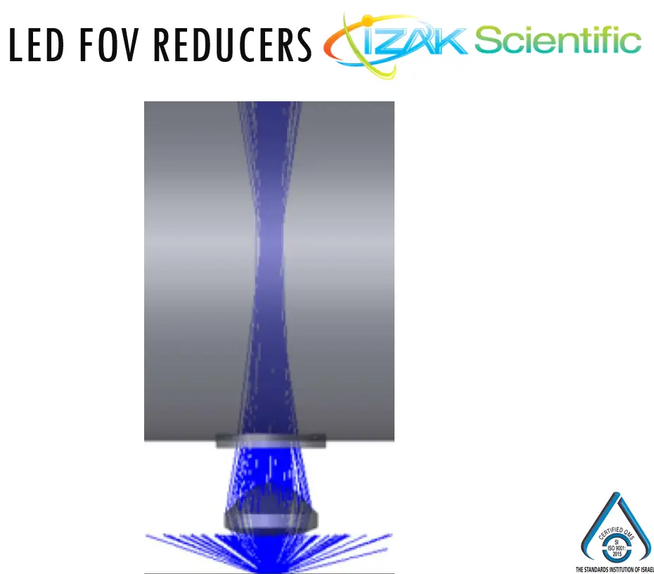
LED field-of-view reducer with a custom molded aspheric lens

LED optics

A low-cost LED field-of-view reducer

Challenge
An LED emits over a wide angle. The product needed a narrow, well-defined beam at a cost that suits volume production.
What we did
We designed the optical layout around a custom aspheric lens: focal length, aperture and position chosen for the target field of view, then adapted the lens for low-cost molded manufacture.
Where it led
Measuring LED angle, intensity and colour is now part of our LED test work.
IZAK test products
Uniform illumination built from laser diodes

Illumination

Uniform illumination from laser diodes

Challenge
Laser-diode beams are elliptical and divergent, unlike the round beams of solid-state or fiber lasers. A simple lens gives a hot spot, not a uniform area.
What we did
We built early prototypes from off-the-shelf optics, measured each iteration with a beam profiler and converged quickly on a layout that gives a uniform field.
Where it led
Fast prototype-and-measure loops with our own beam profilers.
Laser beam profilers
Beam profiler software showing measured values of a CO2 laser beam

Production test

A CO₂ laser test jig that became an LWIR beam profiler

Challenge
In production, small batch-to-batch variations in mounts and optics cause tilt, decentring and spacing errors. The customer needed to check every 10.6 µm CO₂ laser before shipping, at low cost.
What we did
We built a test jig with a low-cost, adaptable beam profiler and software that measures the beam and reports pass or fail.
Where it led
The design grew into our LWIR beam profiler for 7.7–12 µm.
LWIR beam profiler
Selection of optical components: lenses, mirrors, prisms, gratings and fibers

Verification

Choosing and proving a component for a medical device file

Challenge
Several lenses, sensors or light sources looked suitable on paper. The customer had to choose one and prove its performance for the Design History File.
What we did
We reviewed the candidates against the requirement, designed the experiments, measured the functions that matter in our lab and wrote the report with method, data and conclusions.
Where it led
A documented choice, and test methods that can be reused in incoming inspection.
What the report contains

Built on our own instruments

The products behind the projects

We design the test as well as the optics, and we measure with instruments we build and know inside out. When a project needs a measurement that does not exist yet, it often becomes the next product.

UV–VIS–NIR300–1100 nmSWIRup to 2.05 µmMWIR1.5–5.7 µmLWIR7.7–12 µm

Quality

A test report you can file

Medical, defense and communications projects must meet industry standards and regulations. IZAK Scientific is assessed and certified to ISO 9001:2015 for the design and development of electro-optical systems, and every project ends with a report that stands up to review.

  • Requirement, subject and acceptance criteria
  • Devices and technologies reviewed, and why one was chosen
  • Test set-up, instruments and calibration status
  • Raw data, analysis and measurement uncertainty
  • Results against the criteria, conclusions and recommendations
IZAK Scientific ISO 9001:2015 certificate for electro-optics design and development
ISO 9001:2015 certificate, IZAK Scientific.

FAQ

Questions about optical design projects

What does an optical system design project with IZAK include?

A typical project covers the review of candidate components and technologies, the optical and opto-mechanical design, a prototype, a test plan, the measurements themselves and a written report. You can start at any stage: some customers bring a finished design that needs verification, others start from a requirement sheet.

Can you test an optical component or device we already selected?

Yes. We review the device against your requirements, design the experiment, run the tests in our lab and report the measured performance with the method, set-up and uncertainty, so the result can go into your Design History File.

Which wavelengths can you measure?

Our own laser beam profilers cover UV–VIS–NIR from 300 to 1100 nm, SWIR up to 2.05 µm, MWIR from 1.5 to 5.7 µm and LWIR from 7.7 to 12 µm. For spectral and radiometric work we build multi-channel spectro-radiometers matched to the bands of the project.

Do you only design, or can you also build test stations for production?

Both. Several projects on this page started as a one-off lab measurement and became a production test jig: a fixture, the measurement instrument and software with pass/fail limits and reports.

How do we start?

Book a 20-minute call or send the requirement in the contact form: wavelength or band, power or energy, beam or field size, environment and what you need to prove. We reply with the questions that matter and a proposed approach.

Next step

Have an optical problem to solve or prove?

Tell us what the light must do and what you need to show. We reply with the questions that matter and a proposed approach.

  • Wavelength or spectral band
  • Power, energy or radiance
  • Beam, spot or field size
  • Environment and interfaces
  • What the test must prove
Skip to content