fbpx

LED Tester of Color and Position : How does it Work?

General

 LED Tester was designed to detect LED colors and position as a configuration on PCB boards or indication bottoms on electronics. For example, testing indication lights on keyboards or panels in the manufacturing production line. The system includes an imager with optics and software applications. The software application can be an API (DLL file) integrated into other automated testers or as a standalone tester application.

The LED tester API or application only has four commands:

  • Open/Close camera (can work with images instead of the camera)
  • Learning a new configuration: For example, one configuration for one type of PCB and another configuration for a different PCB type. Each PCB type (or other LED configuration) needs a specific configuration file after learning.
  • Test – assessing all LEDs that are currently operated and log results to a *.csv log file (see more information below).


In Figure 1, one can see an example of a PCB board to be tested for LED’s colors, and positions are assembled appropriately

Figure 1: PCB board with 37 LED that used in these tests
Figure 2: PCB board while all LEDs are enabled. Two LEDs are not operated in column 2, row 2, and column 10, row 7 line.

As seen in Figure 2, for convenience, LEDs were segmented into three ROIs: 1, 2, and 3.

After learning the software application, the LED position, and color, the application recognizes non-working LEDs, see Figure 3 in position 1.1 in ROI 1 (column 2 and row 2), and position 5.1 in ROI 3 (column 6 row 2). 

Figure 3: Two LEDs are not operated in purpose for this demo and are marked with white and red rectangles. The non-working LEDs are from column 2, row 2 and column 10, row 7

In Figure 4, one can see how the LED Tester detects LEDs after learning. Each LED has:

1.  Position address in the form of Column. Row such as 1.1, 1.2, etc.

2.  Indication if the LED works appropriately (for example, LED location 1.1 is off).

3.  Matching grade with respect to the reference board that was learned. The matching grade is based on spectrum and intensity analysis. Pass /Failed criteria are based on the matching grade.

The test command is executed without any GUI and provides Pass/Fail test results based on matching grade criteria defined by the user. For example, if matching grade criteria were set to 500, all LEDs that detect with matching grade above 500 are passed, and all other LEDs with matching criteria above 500 are failed.

The API with all commands is shown in Figure 5.

Test command can be run for a single ROI or all ROIs. For example, test results for ROI 1 are shown in Figure 6.

Figure 6: Test results in CSV file for ROI

The LED tester system can save time and money and increase quality assurance in manufacturing for manufacturing managers, testing managers and quality managers in the medical world, sensors manufacturers, electronics manufacturers, assembly factories, and more.

MKS Instruments, Inc.

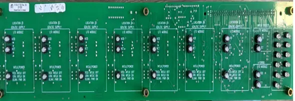
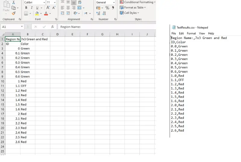
We purchased LED Color and position tester from IZAK Scientific after having successful projects before and due to their great skills and fast delivery. We needed a solution to test different PCBs, with each PCB having a few LED configurations. IZAK Scientific, led by Tzachi, delivered us an API (dll file) for the LED Tester, along with an example in the LabWindows CVI environment. We integrated IZAK’s LED tester in our tester software. In addition, IZAK also delivered a tester box with an imager and optics, along with relays as a system.

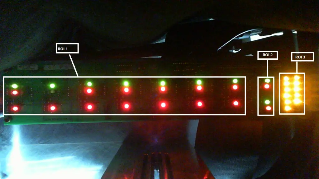
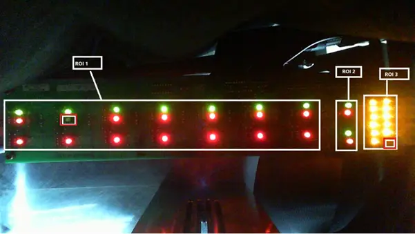
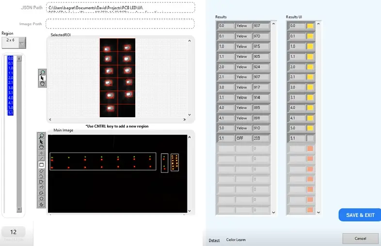
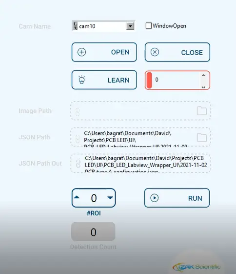
IZAK LED Tester API is a smart and simple, easy-to-learn machine-learning algorithm that learns new PCB in a few minutes. The system allows us to test our PCB quickly and easily in free space configuration. As we integrated the system, we got a full service customized to our specific needs, along with the support from IZAK’s great team.

This was one of few projects we made with Izak Scientific, and the team proved to be professional, with on-time delivery.

Testing Development Manager Automation & Control Solutions

Moshe, MKS Instrument

Chatbot ChatGPT
Chatbot & Knowledge Navigator by Kognetiks
Skip to content