

In short
- The phase-matching angle is only the centre. The angular acceptance tells you how far the beam direction can drift from it before conversion drops by half.
- Acceptance shrinks as 1/L. A 10 mm BBO crystal doubling 1064 nm accepts about 0.85 mrad of external tilt (FWHM); a 2 mm crystal accepts about 4.2 mrad.
- Walk-off sets a second length limit. In BBO the second harmonic drifts away from the fundamental at about 56 mrad (3.2°), so tight focusing and long crystals do not mix.
- Match beam and mount to the crystal. Keep the beam’s full divergence below the acceptance and choose a mount whose tilt resolution is about one tenth of it.
The angular acceptance of a nonlinear crystal is the range of beam directions over which second-harmonic generation (SHG) or spontaneous parametric down-conversion (SPDC) stays efficient. Together with the walk-off angle it decides how long the crystal should be, how hard you can focus, and how fine the tilt adjustment of the crystal mount has to be. Our introduction to nonlinear optics shows how to find the phase-matching angle itself. This application note covers the next step: the tolerances around that angle, with a worked example and a calculator for BBO and KDP, type I and type II.
Why the phase-matching angle is not enough
In birefringent phase matching the crystal is cut and tilted so that the waves travel at the angle θ to the optic axis where the phase mismatch Δk is zero. For type I SHG (o + o → e) that means ne(2ω, θ) = no(ω). Away from that exact angle Δk grows, and the second-harmonic output follows
P2ω ∝ L² · sinc²(ΔkL/2)
where L is the crystal length. The L² factor rewards long crystals, but the sinc² term narrows in proportion: double the length and the tolerance on Δk halves. Every real beam has a spread of directions (its divergence) and a spread of wavelengths (its bandwidth), so part of it always sits off the peak. The design question is not “what is θ?” but “how much of my beam falls inside the sinc² window, and does it still overlap with the generated wave?”
Angular acceptance: how far the crystal can tilt
Expanding Δk to first order around the phase-matching angle gives the full width at half maximum (FWHM) of the sinc² curve:
ΔθFWHM = 5.566 / (L · |∂Δk/∂θ|)
The constant comes from sinc²(x) = ½ at x = 1.392. Three practical points follow:
- It scales as 1/L. Datasheets therefore quote it as a product, in mrad·cm. Divide by the length in cm to get your crystal’s acceptance.
- Internal versus external. The formula gives the angle inside the crystal. When you tilt the crystal, refraction at the input face multiplies the angle by about the refractive index, so the external acceptance is roughly n times larger (about 1.65× for BBO at 1064 nm).
- It applies in one plane only. Critical phase matching is sensitive to tilt in the plane that contains the beam and the optic axis. In the orthogonal plane the tolerance is much wider, which is why a crystal mount’s two tilt axes do not play equal roles.
Published values for the same crystal often differ by a factor of two, because some quote internal and some external angles, and some use the half-width instead of the full width. For BBO, type I SHG of 1064 nm, the model used here gives 0.51 mrad·cm internal and 0.85 mrad·cm external (FWHM). Always check the definition before you compare numbers.
Walk-off: when the beams stop overlapping
In an anisotropic crystal the energy of the extraordinary wave does not travel along its wave vector. It drifts sideways at the walk-off angle ρ:
tan ρ = ½ · ne(θ)² · (1/ne² − 1/no²) · sin 2θ
In type I SHG the ordinary fundamental goes straight and the extraordinary second harmonic drifts away. After a length L the two are displaced by L·tan ρ. Once that displacement is comparable to the beam size, extra crystal length adds little. A useful yardstick is the aperture length
La = √π · w0 / ρ
with w0 the 1/e² beam radius. For BBO at 1064 nm and a 50 µm focus, La is only 1.6 mm. Tight focusing raises intensity but shortens the useful length, so the two limits pull in opposite directions. Non-critical phase matching at θ = 90°, reached by temperature tuning rather than angle, removes walk-off and widens the acceptance, but only for crystal and wavelength pairs that allow it.
| SHG of 1064 nm | θ | Walk-off ρ | Acceptance, internal | External, 10 mm crystal | Spectral acceptance |
|---|---|---|---|---|---|
| BBO type I (o+o→e) | 22.8° | 55.6 mrad (3.19°) | 0.51 mrad·cm | 0.85 mrad | 1.96 nm·cm |
| BBO type II (e+o→e) | 32.8° | 67.6 mrad (3.87°) | 0.80 mrad·cm | 1.32 mrad | 2.12 nm·cm |
| KDP type I (o+o→e) | 41.2° | 28.0 mrad (1.60°) | 1.13 mrad·cm | 1.68 mrad | 20.7 nm·cm |
| KDP type II (e+o→e) | 59.1° | 20.0 mrad (1.15°) | 2.19 mrad·cm | 3.24 mrad | 20.2 nm·cm |
Model values from published room-temperature dispersion equations; FWHM; spectral acceptance refers to the fundamental. Type II walk-off is that of the extraordinary fundamental. Cut angles from crystal suppliers may differ by a few tenths of a degree.
The trade-off is clear: BBO has a much larger nonlinear coefficient, but a narrower angular window and stronger walk-off than KDP. That is why short BBO crystals are standard for ultrafast and SPDC work, while long KDP crystals suit large, low-divergence beams.
Spectral acceptance for short pulses
The same sinc² logic applies to wavelength. At a fixed angle, a change in the fundamental wavelength changes Δk through the group-velocity mismatch between the fundamental and the second harmonic. For type I BBO at 800 nm the mismatch is about 194 fs/mm, which gives a spectral acceptance of about 4.9 nm (FWHM) for a 1 mm crystal. A 100 fs transform-limited sech² pulse at 800 nm has a bandwidth of about 6.7 nm, so a 1 mm crystal clips its spectrum; a 0.5 mm crystal (9.8 nm) does not. For nanosecond lasers with sub-nanometre linewidths, spectral acceptance rarely matters and the angular limit dominates.
Worked example: SHG of a Q-switched 1064 nm laser
A Q-switched 1064 nm laser with M² = 1.2 is to be doubled to 532 nm in BBO, type I. Peak intensity is already high, so the beam is not focused hard: w0 = 0.4 mm (0.8 mm 1/e² diameter) in the crystal. The full divergence in air is
Θ = 2 · M² · λ / (π · w0) = 2 × 1.2 × 1.064 µm / (π × 400 µm) = 2.03 mrad
| Crystal length | External acceptance | Divergence / acceptance | Walk-off at exit | Verdict |
|---|---|---|---|---|
| 2 mm | 4.23 mrad | 0.48 | 111 µm | Inside the window |
| 5 mm | 1.69 mrad | 1.20 | 278 µm | Marginal, divergence-limited |
| 10 mm | 0.85 mrad | 2.40 | 557 µm | Divergence-limited |
| 10 mm, w0 = 1.0 mm | 0.85 mrad | 0.96 | 557 µm | Acceptable |
With w0 = 0.4 mm the aperture length La is 12.7 mm, so walk-off is not yet the limit; divergence is. Going from 5 to 10 mm buys far less than the L² factor promises, because more than half of the beam’s angular spread falls outside the window. Expanding the beam to w0 = 1.0 mm cuts the divergence to 0.81 mrad, brings the ratio to 0.96 and raises La to 32 mm, at the cost of lower intensity. The choice between “short crystal, small beam” and “long crystal, large beam” then depends on the available pulse energy and the damage threshold.
The mount has to hold the crystal at the peak to a small fraction of the window. For the 10 mm crystal the external FWHM is 0.85 mrad (0.049°), so a tilt resolution of about 85 µrad is a sensible target; for the 2 mm crystal about 0.42 mrad is enough. The same numbers tell you how much a few microradians of thermal drift in the mount will cost.
SPDC with a 405 nm pump. For degenerate type I SPDC (405 nm → 810 + 810 nm) the phase-matching condition is the same as for SHG of 810 nm: θ = 28.8° in BBO. A 2 mm crystal has an external acceptance of 2.7 mrad for collinear emission, and a pump with w0 = 300 µm diverges by 0.86 mrad, a ratio of 0.32. Small tilts of the crystal open or close the emission cone, so tilt resolution sets how repeatably you can return to collinear or a chosen cone angle. In type II sources, walk-off also displaces the two polarisations relative to each other, which is why compensation crystals are common in entangled-photon set-ups; our article on photon entanglement describes how such sources are used.
Angular acceptance and walk-off calculator
Choose SHG or degenerate SPDC, the crystal and the phase-matching type. The tool solves θ and computes walk-off, internal and external angular acceptance (FWHM), the divergence of your beam, the walk-off aperture length and the tilt resolution to aim for.
Room-temperature dispersion models, valid for all waves between about 0.2 and 2.6 µm. External values use small-angle refraction at a face normal to the beam. The tilt-resolution target is one tenth of the external FWHM. Spectral acceptance refers to the fundamental and is shown for SHG only.
What the crystal mount has to deliver
The numbers above translate directly into mount requirements:
- Fine tip and tiltResolution near one tenth of the external acceptance, with the tuning axis set in the critical plane.
- Lateral translationTo centre a small beam in the crystal aperture, allow for walk-off at the exit face, and move to a fresh spot if the surface degrades.
- Mechanical stabilityDrift of a fraction of a milliradian moves a long BBO crystal off its peak, so a rigid, compact mount matters as much as resolution.
- Temperature controlRefractive indices change with temperature, shifting the phase-matching angle; stabilising the crystal keeps the optimum where you set it.
- High-voltage accessFor electro-optic crystals (Pockels cells, Q-switches) the same mount must carry the drive voltage to the crystal safely.
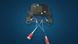
The IZAK QuantumAlign NLO kinematic stage was built around these needs: X–Y translation with sub-micrometre-class adjustment, high-resolution tip and tilt about two axes for phase matching in SHG, SPDC, SFG, DFG and OPO, an integrated high-voltage connection to the crystal, and optional thermoelectric temperature stabilisation with feedback. It holds crystals up to 5 mm × 5 mm in cross-section, which comfortably fits the beam sizes and walk-off displacements in the example above.
To verify the beam you are sending into the crystal, measure its waist and divergence first; our guides to measuring laser beam divergence and M² measurement show how. A camera UV–VIS–NIR beam profiler covering 300–1100 nm sees the 1064 nm fundamental, the 532 nm second harmonic, a 405 nm pump and an 810 nm alignment laser that stands in for the photon-pair path, so you can check size and overlap at every stage.
Common alignment mistakes
- Tuning the wrong axis. Only tilt in the critical plane tunes phase matching sharply. Identify it from the crystal cut marking before you start.
- Focusing as hard as possible. A tight focus in a long, high-walk-off crystal often gives less output than a looser one, because divergence and walk-off both exceed their limits.
- Comparing datasheets blindly. Internal versus external angles and FWHM versus half-width can hide a factor of three between “equal” specifications.
- Ignoring polarisation. Type I needs both fundamental photons in the ordinary polarisation; a wave plate before the crystal is usually cheaper than re-cutting it.
- Forgetting heating. At high average power, absorption warms the crystal and shifts the optimum angle; re-peak after warm-up or stabilise the temperature.
IZAK products for this application
Precise crystal positioning and a well-characterised input beam are the two halves of efficient, repeatable frequency conversion.
 Nonlinear opticsQuantumAlign NLO Kinematic StageX–Y, tip/tilt, high voltage and optional temperature control for crystals up to 5 × 5 mm.View product →
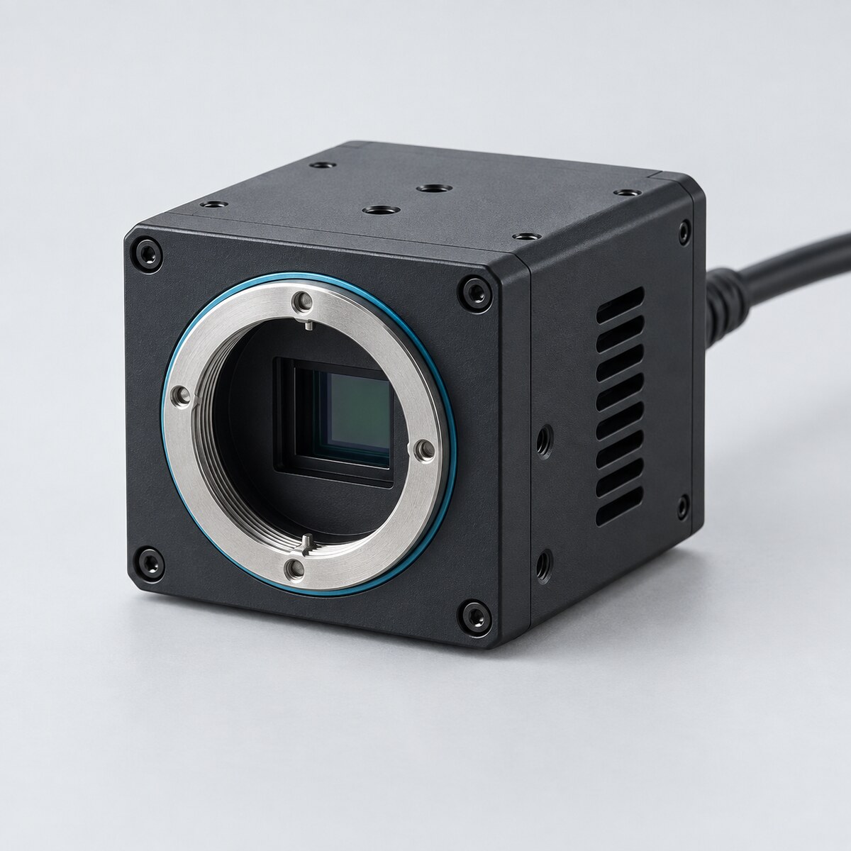 300–1100 nmUV–VIS–NIR Laser Beam ProfilersMeasure waist, divergence and overlap of pump and generated beams.View product →
Building a complete frequency-conversion or photon-pair source? See our electro-optical system design services.
Frequently asked questions
QWhat is the angular acceptance of a nonlinear crystal?
QHow do I choose the crystal length for SHG?
QWhat tilt resolution does a crystal mount need?
Tzachi Sabati
CEO, IZAK Scientific
Physicist specializing in photonics and quantum technologies, with deep expertise in quantum sensors and advanced optical systems. Leads the Advanced Quantum Lab course at the Technion, bridging academic excellence with industry innovation. At IZAK Scientific, provides cutting-edge photonics-based solutions, developing customized inspection and sensing systems for R&D and production. Passionate about advancing quantum sensing applications and integrating novel technologies to meet industry needs.
